
Installation Guide Owner manual

Cello Installation Guide Installation
MAN-CELIG (Ver. 1.602)
www.elmomc.com
46
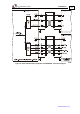
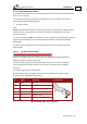
3.4.8 I/O Cables
The Cello has two I/O ports, J1 and J2. J1 is a general I/O which can be used to connect 6 digital
inputs and 5 digital outputs. J2 is an input port for connecting up to 4 separate digital inputs
and 2 analog inputs:
I/O J1 Port J2 Port Total
Digital Input 6 4 10
Digital Output 5 - 5
Analog Input - 2 2
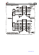
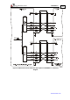
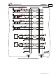
3.4.8.1 General I/O Port (J1)
Port J1 has a 15-pin high density D-Sub plug. When assembling this I/O cable, follow the
instructions in Section 3.4.4 (Feedback and Control Cable Assemblies) using a 15-pin high
density metal case D-Sub female connector (socket).
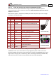
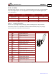
Pin Signal Function Pin Positions
1 IN1 Programmable input 1
2 IN2 Programmable input 2
3 IN3 Programmable input 3
4 OUT2 Programmable output 2
5 OUT3 Programmable output 3
6 IN4 Programmable input 4
7 IN7 Programmable input 7
8 IN8 Programmable input 8
9 INRET General input return
10 OUTRET2-3 Programmable output return 2 & 3
11 OUT4 Programmable output 4
12 OUTRET4-5 Programmable output return 4 & 5
13 OUT5 Programmable output 5
14 OUT1 Programmable output 1
15 OUTRET 1 Programmable output return 1
Table 13: J1 I/O Cable - Pin Assignments