
Owner manual


Drum HV (High Voltage) Installation Guide Installation
MAN-DRU-HVIG (Ver. 1.602)
www.elmomc.com
53
3.5.8.4. Pulse-and-Direction Input Option on FEEDBACK B (YA[4]=0)
This mode is used for input of differential or single-ended pulse-and-direction position
commands on Port B1. In this mode Port B2 provides differential buffered pulse-and-direction
outputs for another axis.
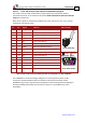
Below are the signals on the Auxiliary Feedback ports when they are set up to run as a single-
ended pulse-and-direction input:
Port Pin Signal Function Pin Positions
B1 1 PULS/CHA Pulse/Auxiliary channel A high input
15-Pin D-Sub Plug
2 NC Do not connect this pin
B1 3 DIR/CHB Direction/Auxiliary channel B high input
4
NC
Do not connect this pin
5
NC
Do not connect this pin
B2 6 CHAO Channel A output
B2
7
CHAO-
Channel A complement output
PWR 8 +5V Encoder supply voltage
PWR 9 SUPRET Encoder supply voltage return
5
15
10
1
11
6
Port B1
Port B2
Power
N.C.
15-Pin D-Sub Socket
10 NC Do not connect this pin
B2
11
CHBO
Channel B output.
B2 12 CHBO- Channel B complement output
13
NC
Do not connect this pin
14 NC Do not connect this pin
PWR 15 SUPRET Supply return
Table 14: Pulse-and-Direction Auxiliary Encoder Pin Assignment on AUX. FEEDBACK
AUX. FEEDBACK on the Drum HV (High Voltage) has a 15-pin high density D-Sub socket.
Connect the Auxiliary Feedback cable from the Pulse and Direction Controller to AUX.
FEEDBACK using a 15-pin, high density D-Sub plug with a metal housing. When assembling the
Auxiliary Feedback cable, follow the instructions in Section 3.5.5 (Feedback and Control
Assemblies).