Guitar Digital Servo Drive Installation Guide July 2014 (Ver. 1.601) www.elmomc.
Notice This guide is delivered subject to the following conditions and restrictions: • This guide contains proprietary information belonging to Elmo Motion Control Ltd. Such information is supplied solely for the purpose of assisting users of the Guitar servo drive in its installation. • The text and graphics included in this manual are for the purpose of illustration and reference only. The specifications on which they are based are subject to change without notice.
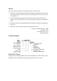
Revision History Version Details 1.0 April 2008 Initial release 1.1 July 2008 Heat dissipation data added in Chapter 3 1.2 April 2009 Updated Section 3.8.3; added Section 3.16 1.3 March 2010 MTCR 01-010-01: Updated Figure 22 1.4 July 2010 Updated Sections 3.4 and 4.1.8 1.5 July 2012 Formatted according to new template “Metronome” was replaced by the “Composer” software. 1.501 February 2013 Added a caution and recommendation on the type of cleaning solution to use for the Elmo unit. 1.
Elmo Worldwide Head Office Elmo Motion Control Ltd. 60 Amal St., P.O. Box 3078, Petach Tikva 49516 Israel Tel: +972 (3) 929-2300 • Fax: +972 (3) 929-2322 • info-il@elmomc.com North America Elmo Motion Control Inc. 42 Technology Way, Nashua, NH 03060 USA Tel: +1 (603) 821-9979 • Fax: +1 (603) 821-9943 • info-us@elmomc.com Europe Elmo Motion Control GmbH Hermann-Schwer-Strasse 3, 78048 VS-Villingen Germany Tel: +49 (0) 7721-944 7120 • Fax: +49 (0) 7721-944 7130 • info-de@elmomc.
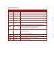
Guitar Installation Guide MAN-GUIIG (Ver. 1.601) Table of Contents Chapter 1: 1.1. 1.2. 1.3. 1.4. 1.5. Warnings......................................................................................................................... 9 Cautions .......................................................................................................................... 9 Directives and Standards ..............................................................................................
Guitar Installation Guide Table of Contents MAN-GUIIG (Ver. 1.601) 3.11. 3.12. 3.13. 3.14. 3.15. 3.16. 3.10.1. Main and Auxiliary Feedback Combinations ................................................. 37 3.10.2. Auxiliary Feedback: Emulated Encoder Output Option (YA[4]=4)................. 38 3.10.3. Auxiliary Feedback: Single-Ended Encoder Input Option (YA[4]=2) .............. 40 3.10.4. Auxiliary Feedback: Pulse-and-Direction Input Option (YA[4]=0) ................. 43 I/Os ........................
Guitar Installation Guide Table of Contents MAN-GUIIG (Ver. 1.601) 4.8.2.3. Interpolated Analog (Sine/Cosine) Encoder ................................. 68 4.8.2.4. Resolver ........................................................................................ 68 4.8.2.5. Tachometer................................................................................... 69 4.8.2.6. Potentiometer .............................................................................. 69 4.8.3.
Guitar Installation Guide 8 MAN-GUIIG (Ver. 1.601) Chapter 1: Safety I nform ation In order to operate the Guitar servo drive safely, it is imperative that you implement the safety procedures included in this installation guide. This information is provided to protect you and to keep your work area safe when operating the Guitar and accompanying equipment. Please read this chapter carefully before you begin the installation process.
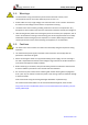
Guitar Installation Guide Safety Information MAN-GUIIG (Ver. 1.601) 1.1. Warnings • To avoid electric arcing and hazards to personnel and electrical contacts, never connect/disconnect the servo drive while the power source is on. • Power cables can carry a high voltage, even when the motor is not in motion. Disconnect the Guitar from all voltage sources before it is opened for servicing. • The Guitar servo drive contains grounding conduits for electric current protection.
Safety Information Guitar Installation Guide MAN-GUIIG (Ver. 1.601) 1.3.
Guitar Installation Guide 11 MAN-GUIIG (Ver. 1.601) Chapter 2: I ntroduction This installation guide describes the Guitar servo drive and the steps for its wiring, installation and power-up. Following these guidelines ensures maximum functionality of the drive and the system to which it is connected. 2.1. Drive Description The Guitar series of digital servo drives is designed to deliver “the highest density of power and intelligence”. The Guitar delivers up to 4.8 kW of continuous power or 8.
Guitar Installation Guide Introduction MAN-GUIIG (Ver. 1.601) 2.2. Product Features 2.2.1. Current Control • Fully digital • Sinusoidal commutation with vector control or trapezoidal commutation with encoder and/or digital Hall sensors • 12-bit current loop resolution • Automatic gain scheduling, to compensate for variations in the DC bus power supply 2.2.2.
Introduction Guitar Installation Guide MAN-GUIIG (Ver. 1.601) 2.2.4. Advanced Position Control This relates to the Advanced model only. • Position-based and time-based ECAM mode that supports a non-linear follower mode, in which the motor tracks the master motion using an ECAM table stored in flash memory • Dual (position/velocity) loop 2.2.5.
Guitar Installation Guide Introduction MAN-GUIIG (Ver. 1.601) 2.3. System Architecture Figure 1: Guitar System Block Diagram 2.4. How to Use this Guide In order to install and operate your Elmo Guitar servo drive, you will use this manual in conjunction with a set of Elmo documentation.
Introduction Guitar Installation Guide MAN-GUIIG (Ver. 1.
Guitar Installation Guide 16 MAN-GUIIG (Ver. 1.601) Chapter 3: I nstallation The Guitar must be installed in a suitable environment and properly connected to its voltage supplies and the motor. 3.1. Site Requirements You can guarantee the safe operation of the Guitar by ensuring that it is installed in an appropriate environment.
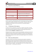
Installation Guitar Installation Guide MAN-GUIIG (Ver. 1.601) The part number at the top gives the type designation as follows: 4. Verify that the Guitar type is the one that you ordered, and ensure that the voltage meets your specific requirements. 3.3. Pinouts The Guitar has nine connectors. 3.3.1. Connector Types Pins Type 2x16 2 mm Pitch 0.
Installation Guitar Installation Guide MAN-GUIIG (Ver. 1.601) 3.3.2.
Installation Guitar Installation Guide MAN-GUIIG (Ver. 1.601) Pin (J1) Signal Function 28 COMRET Common return 29 AUX PORT INDEX Auxiliary port index (bidirectional) 30 CAN_COMRET CAN communication return 31 CAN_L CAN_L busline (dominant low) 32 CAN_H CAN_H busline (dominant high) 3.3.3.
Installation Guitar Installation Guide MAN-GUIIG (Ver. 1.601) 3.4. Mounting the Guitar The Guitar was designed for mounting on a printed circuit board (PCB) via 2 mm pitch 0.51 mm square pins. When integrating the Guitar into a device, be sure to leave about 1 cm (0.4") outward from the heatsink to enable free air convection around the drive. We recommend that the Guitar be soldered directly to the board.
Installation Guitar Installation Guide MAN-GUIIG (Ver. 1.601) 3.5. Integrating the Guitar on a PCB The Guitar is designed to be mounted on a PCB, either by soldering its pins directly to the PCB or by using suitable socket connectors. In both cases the following rules apply: 3.5.1. Traces 1. The size of the traces on the PCB (thickness and width) is determined by the current carrying capacity required by the application.
Guitar Installation Guide Installation MAN-GUIIG (Ver. 1.601) The returns above are all shorted within the Guitar in a topology that results in optimum performance. 1. When wiring the traces of the above functions, on the Integration Board, the Returns of each function must be wired separately to its designated terminal on the Guitar. DO NOT USE A COMMON GROUND PLANE. Shorting the commons on the Integration Board may cause performance degradation (ground loops, etc). 2.
Guitar Installation Guide Installation MAN-GUIIG (Ver. 1.601) 3.6. The Guitar Connection Diagram Figure 4: The Guitar Connection Diagram www.elmomc.
Installation Guitar Installation Guide MAN-GUIIG (Ver. 1.601) 3.7. Main Power and Motor Power The Guitar receives power from the main power supply and delivers power to the motor. Pin Function Cable Pin Positions VP+ Pos.
Installation Guitar Installation Guide MAN-GUIIG (Ver. 1.601) 3.7.2. Connecting Main Power Connect the VP+, PR and PE pins on the Guitar in the manner described in Section 3.5 (Integrating the Guitar on a PCB). Note: The source of the 12 to 195 VDC Main Power Supply must be isolated. Figure 6: Main Power Supply Connection Diagram (no Auxiliary Supply) 3.8. Auxiliary Supply (for drive logic) Notes for auxiliary supply connections: • The source of the Auxiliary Supply must be isolated.
Guitar Installation Guide Installation MAN-GUIIG (Ver. 1.601) 3.8.1. Single Supply A single isolated DC power supply can provide power for both the main power and the Auxiliary (Drive Logic) Supply. Figure 7 shows how a single supply is connected. In this configuration, there is no backup functionality upon power shutdown. Figure 7: Single Supply for both the Main Power Supply and the Auxiliary Supply 3.8.2.
Guitar Installation Guide Installation MAN-GUIIG (Ver. 1.601) 3.8.3. Shared Supply A "Main" DC Power Supply can be designed to supply power to the drive's logic as well as to the Main Power (see Figure 7 and the upper portion of Figure 9). If backup functionality is required for continuous operation of the drive’s logic in the event of a main power-out, a backup supply can be connected by implementing “diode coupling” (see the Aux. Backup Supply in Figure 9).
Installation Guitar Installation Guide MAN-GUIIG (Ver. 1.601) 3.9. 28 Main Feedback The Main Feedback port is used to transfer feedback data from the motor to the drive.
Guitar Installation Guide Installation MAN-GUIIG (Ver. 1.601) Figure 10: Main Feedback - Incremental Encoder with Digital Hall Sensors Connection Diagram www.elmomc.
Guitar Installation Guide Installation MAN-GUIIG (Ver. 1.601) Figure 11: Main Feedback – Interpolated Analog (Sine/Cosine) Encoder Connection Diagram www.elmomc.
Guitar Installation Guide Installation MAN-GUIIG (Ver. 1.601) Figure 12: Main Feedback – Interpolated Analog (Sine/Cosine) Encoder with Digital Hall Sensors Connection Diagram www.elmomc.
Installation Guitar Installation Guide MAN-GUIIG (Ver. 1.601) Figure 13: Main Feedback – Resolver Connection Diagram www.elmomc.
Guitar Installation Guide Installation MAN-GUIIG (Ver. 1.601) Figure 14: Main Feedback – Resolver and Digital Hall Sensors Connection Diagram www.elmomc.
Guitar Installation Guide Installation MAN-GUIIG (Ver. 1.601) Figure 15: Main Feedback – Tachometer Feedback with Digital Hall Sensors Connection Diagram for Brushless Motors Figure 16: Main Feedback – Tachometer Feedback Connection Diagram for Brush Motors www.elmomc.
Guitar Installation Guide Installation MAN-GUIIG (Ver. 1.601) Figure 17: Main Feedback – Potentiometer Feedback with Digital Hall Sensors Connection Diagram for Brushless Motors Figure 18: Main Feedback – Potentiometer Feedback Connection Diagram for Brush Motors and Voice Coils www.elmomc.
Guitar Installation Guide Installation MAN-GUIIG (Ver. 1.601) 3.10. Auxiliary Feedback For auxiliary feedback, select one of the following options: a. Single-ended emulated encoder outputs, used to provide emulated encoder signals to another controller or drive. The Emulated Encoder Output Option is only available when using a Resolver, Analog Encoder, Tachometer, Potentiometer or Absolute Encoder as the main feedback device. The absolute model provides differential emulated encoder output.
Installation Guitar Installation Guide MAN-GUIIG (Ver. 1.601) 3.10.1. 37 Main and Auxiliary Feedback Combinations The Main Feedback is always used in motion control devices whereas Auxiliary Feedback is often, but not always used. The Auxiliary Feedback connector on the Guitar has three bidirectional pins (CHA, CHB and INDEX). When used in combination with Main Feedback, the Auxiliary Feedback can be set, by software, as follows: Main Feedback Auxiliary Feedback Software Setting YA[4] = 4 (Aux.
Installation Guitar Installation Guide MAN-GUIIG (Ver. 1.601) Main Feedback 38 Auxiliary Feedback Typical Applications 3.10.2. Pin (J1) Analog Encoder applications where position data is required in the Encoder’s quadrature format. Any application where two feedbacks are used by the drive. Any application where two feedbacks are used by the drive. Resolver applications where position data is required in the Encoder’s quadrature format.
Guitar Installation Guide Installation MAN-GUIIG (Ver. 1.601) Figure 19: Emulated Encoder Direct Output – Acceptable Connection Diagram Figure 20: Emulated Encoder Buffered Output – Recommended Connection Diagram www.elmomc.
Installation Guitar Installation Guide MAN-GUIIG (Ver. 1.601) Figure 21: Emulated Encoder Differential Output – Highly Recommended Connection Diagram 3.10.3. Pin (J1) Auxiliary Feedback: Single-Ended Encoder Input Option (YA[4]=2) Signal Function 27 +5 V Encoder supply voltage 6 SUPRET Supply return 29 INDEX Auxiliary index input 5 CHB Auxiliary channel B input 4 CHA Auxiliary channel A input Pin Positions Note: The Guitar’s Auxiliary Feedback is single-ended.
Guitar Installation Guide Installation MAN-GUIIG (Ver. 1.601) Figure 22: Single-ended Auxiliary Encoder Input - Acceptable Connection Diagram www.elmomc.
Guitar Installation Guide Installation MAN-GUIIG (Ver. 1.601) Figure 23: Single-Ended Auxiliary Encoder Input - Recommended Connection Diagram www.elmomc.
Installation Guitar Installation Guide MAN-GUIIG (Ver. 1.601) Figure 24: Differential Auxiliary Encoder Input – Highly Recommended Connection Diagram 3.10.4. Pin (J1) Auxiliary Feedback: Pulse-and-Direction Input Option (YA[4]=0) Signal Function 28 COMRET Common return 5 DIR/CHB Direction input (push/pull 5 V or open collector) 4 PULS/CHA Pulse input (push/pull 5 V or open collector) Pin Positions Note: The Guitar’s Auxiliary Feedback is single-ended.
Guitar Installation Guide Installation MAN-GUIIG (Ver. 1.601) Figure 25: Pulse-and-Direction Auxiliary Encoder Input – Direct Connection Diagram Figure 26: Pulse-and-Direction Auxiliary Encoder Input – Buffered Connection Diagram www.elmomc.
Guitar Installation Guide Installation MAN-GUIIG (Ver. 1.601) Figure 27: Pulse-and-Direction Auxiliary Encoder Input – Differential Connection Diagram, Highly Recommended www.elmomc.
Installation Guitar Installation Guide MAN-GUIIG (Ver. 1.601) 3.11. I/Os The Guitar has 6 Digital Inputs, 4 Digital Outputs and 1 Analog Input. I/O J1 J2 Total Digital Input 6 - 6 Digital Output 4 - 2 Analog Input - 1 1 3.11.1. Digital Input Each of the pins below can function as an independent input.
Guitar Installation Guide Installation MAN-GUIIG (Ver. 1.601) Figure 28: Digital Input Connection Diagram www.elmomc.
Installation Guitar Installation Guide MAN-GUIIG (Ver. 1.601) 3.11.2.
Guitar Installation Guide Installation MAN-GUIIG (Ver. 1.601) Figure 29: Digital Output Connection Diagram www.elmomc.
Installation Guitar Installation Guide MAN-GUIIG (Ver. 1.601) 3.11.3. Pin (J2) Analog Input Signal Function 3 ANLIN1+ Analog input 1+ 4 ANLIN1- Analog input 1- 2 ANLRET Analog ground Pin Positions Table 9: Analog Input Pin Assignments Figure 30: Analog Input with Single-Ended Source www.elmomc.
Installation Guitar Installation Guide MAN-GUIIG (Ver. 1.601) 3.12. Communications The communication interface may differ according to the user’s hardware. The Guitar can communicate using the following options: a. RS-232, full duplex b. CAN RS-232 communication requires a standard, commercial 3-core null-modem cable connected from the Guitar to a serial interface on the PC. The interface is selected and set up in the Composer software.
Guitar Installation Guide Installation MAN-GUIIG (Ver. 1.601) Figure 31: RS-232 Connection Diagram 3.12.2. CAN Communication Notes for connecting the CAN communication cable: • Connect the shield to the ground of the host (PC). Usually, this connection is soldered internally inside the connector at the PC end. You can use the drain wire to facilitate connection. • Ensure that the shield of the cable is connected to the shield of the connector used for communications.
Guitar Installation Guide Installation MAN-GUIIG (Ver. 1.601) Figure 32: CAN Network Diagram Caution: When installing CAN communication, ensure that each servo drive is allocated a unique ID. Otherwise, the CAN network may hang. www.elmomc.
Guitar Installation Guide Installation MAN-GUIIG (Ver. 1.601) 3.13. Powering Up After the Guitar is connected to its device, it is ready to be powered up. Caution: Before applying power, ensure that the DC supply is within the specified range and that the proper plus-minus connections are in order. 3.14. Initializing the System After the Guitar has been connected and mounted, the system must be set up and initialized. This is accomplished using the Composer, Elmo’s Windows-based software application.
Guitar Installation Guide Installation MAN-GUIIG (Ver. 1.601) 3.15.2. Heat Dissipation Data Heat Dissipation is shown in graphically below: www.elmomc.
Guitar Installation Guide Installation MAN-GUIIG (Ver. 1.601) www.elmomc.
Guitar Installation Guide Installation MAN-GUIIG (Ver. 1.601) 3.15.3. How to Use the Charts The charts above are based upon theoretical worst-case conditions. Actual test results show 30% to 50% better power dissipation. To determine if your application needs a heatsink: 1. Allow maximum heatsink temperature to be 80 °C or less. 2. Determine the ambient operating temperature of the Guitar. 3.
Installation Guitar Installation Guide MAN-GUIIG (Ver. 1.601) 3.16. Evaluation Board and Cable Kit A circuit board is available for evaluating the Guitar. It comes with standard terminal blocks for power connections and D-Sub plugs/sockets for signals connections. The Evaluation Board is provided with a cable kit. Figure 33: The Evaluation Board (can be ordered separately) Evaluation Board Evaluation Board User Manual Catalog Number: EVA-WHI/GUI/BEL MAN-EVLBRD-WHI_BEL_GUI-UG.
Guitar Installation Guide 59 MAN-GUIIG (Ver. 1.601) Chapter 4: Technical Specifications This chapter provides detailed technical information regarding the Guitar. This includes its dimensions, power ratings, the environmental conditions under which it can be used, the standards to which it complies and other specifications. 4.1. Features The Guitar's features determine how it controls motion, as well as how it processes host commands, feedback and other input. 4.1.1.
Guitar Installation Guide Technical Specifications MAN-GUIIG (Ver. 1.601) 4.1.5.
Guitar Installation Guide Technical Specifications MAN-GUIIG (Ver. 1.601) 4.1.7. Built-In Protection • Software error handling • Abort (hard stops and soft stops) • Status reporting • Protection against: Shorts between motor power outputs Shorts between motor power outputs and power input/return Failure of internal power supplies Over-heating • Continuous temperature measurement.
Guitar Installation Guide Technical Specifications MAN-GUIIG (Ver. 1.601) 4.2. Guitar Dimensions www.elmomc.
Technical Specifications Guitar Installation Guide MAN-GUIIG (Ver. 1.601) R35/100 R75/60 R45/60 R75/48 R45/48 50/100 25/100 20/100 35/60 25/60 20/60 Feature 35/48 Power Ratings up to 100 V Models Units 4.3.
Technical Specifications Guitar Installation Guide MAN-GUIIG (Ver. 1.601) Minimum supply voltage VDC 46 Nominal supply voltage VDC 170 Maximum supply voltage VDC 195 Maximum auxiliary supply voltage VDC 195 Maximum continuous power output W Efficiency at rated power (at nominal conditions) % 480 960 1600 2700 R30/200 20/200 17/200 10/200 Units Feature 6/200 Power Ratings for 200 V Models 3/200 4.4.
Technical Specifications Guitar Installation Guide MAN-GUIIG (Ver. 1.601) 4.6.
Technical Specifications Guitar Installation Guide MAN-GUIIG (Ver. 1.601) 4.7.2.
Technical Specifications Guitar Installation Guide MAN-GUIIG (Ver. 1.601) 4.8. Feedbacks 4.8.1. Feedback Supply Voltage The Guitar has two feedback ports (Main and Auxiliary). The Guitar supplies voltage only to the main feedback device and to the auxiliary feedback device if needed. Feature Details Main encoder supply voltage 5 V ±5% @ 200 mA maximum Auxiliary encoder supply voltage 5 V ±5% @ 200 mA maximum 4.8.2.
Technical Specifications Guitar Installation Guide MAN-GUIIG (Ver. 1.601) 4.8.2.2. Digital Halls Feature Details Halls inputs • HA, HB, HC. • Single ended inputs • Built in hysteresis of 1 V for noise immunity Input voltage Nominal operating range: 0 V < VIn_Hall < 5 V Maximum absolute: -1 V < VIn_Hall < 15 V High level input voltage: V InHigh > 2.5 V Low level input voltage: V InLow < 1 V Input current Sink current (when input pulled to the common): 5 mA Maximum frequency fMAX : 2 kHz 4.8.2.
Technical Specifications Guitar Installation Guide MAN-GUIIG (Ver. 1.601) Feature Details Resolver transfer ratio 0.5 Reference frequency 1/Ts (Ts = sample time in seconds) Reference voltage Supplied by the Guitar Reference current up to ±50 mA Encoder outputs See Auxiliary Encoder Output specifications (4.8.3) 4.8.2.5.
Technical Specifications Guitar Installation Guide MAN-GUIIG (Ver. 1.601) 4.8.3. Auxiliary Feedback Port (output mode YA[4]= 4) Feature Details Emulated output • A, B, Index • Single ended Output current capability Maximum output current: IOH (max) = 2 mA High level output voltage: VOH > 3.0 V Minimum output current: IOL = 2 mA Low level output voltage: VOL < 0.
Technical Specifications Guitar Installation Guide MAN-GUIIG (Ver. 1.601) 4.8.4. Auxiliary Feedback Port (input mode YA[4]= 2, 0) Feature Details Encoder input, pulse and direction input Input voltage • A, B, Index • Single ended VIn Low: 0 V < VIL < 0.8 V VIn High: 2 V < VIH < 5 V Maximum absolute voltage: 0 < VIn < 5.
Technical Specifications Guitar Installation Guide MAN-GUIIG (Ver. 1.601) 4.9. I/Os The Guitar has: • • • 6 Digital Inputs 4 Digital Outputs 1 Analog Input 4.9.1. Digital Input Interfaces Feature Details Type of input • Optically isolated • Each input has its own return Input current for all inputs Iin = 2.4 mA @ Vin = 5 V High-level input voltage 2.
Technical Specifications Guitar Installation Guide MAN-GUIIG (Ver. 1.601) 4.9.2. Digital Output Interface Feature Details Type of output • Optically isolated • Open collector and open emitter Maximum supply output (VCC) 30 V Max. output current Iout (max) (Vout = Low) Iout (max) ≤ 15 mA VOL at maximum output voltage (low level) Vout (on) ≤ 0.3 V RL The external resistor RL must be selected to limit the output current to no more than 15 mA.
Technical Specifications Guitar Installation Guide MAN-GUIIG (Ver. 1.601) 4.10. Communications Specification Details RS-232 Signals: • RxD , TxD , Gnd • Full duplex, serial communication for setup and control. • Baud Rate of 9,600 to 57,600 bit/sec. CAN CAN bus Signals: • CAN_H, CAN_L, CAN_GND • Maximum Baud Rate of 1 Mbit/sec. Version: • DS 301 V4.01 Layer Setting Service and Protocol Support: • DS 305 Device Profile (drive and motion control): • DS 402 4.11.
Technical Specifications Guitar Installation Guide MAN-GUIIG (Ver. 1.601) 4.12. Compliance with Standards Specification Details Quality Assurance ISO 9001:2008 Quality Management Design Approved IEC/EN 61800-5-1, Safety Printed wiring for electronic equipment (clearance, creepage, spacing, conductors sizing, etc.) MIL-HDBK- 217F Reliability prediction of electronic equipment (rating, de-rating, stress, etc.
Technical Specifications Guitar Installation Guide MAN-GUIIG (Ver. 1.