
Installation Guide Owner's manual

Guitar Installation Guide Installation
MAN-GUIIG (Ver. 1.601)
www.elmomc.com
40
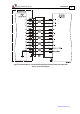
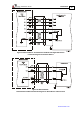
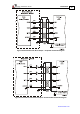
Figure 21: Emulated Encoder Differential Output – Highly Recommended Connection Diagram
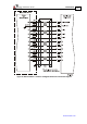
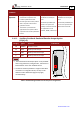
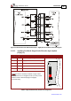
3.10.3. Auxiliary Feedback: Single-Ended Encoder Input Option
(YA[4]=2)
Pin (J1) Signal Function Pin Positions
27 +5 V Encoder supply voltage
6 SUPRET Supply return
29 INDEX Auxiliary index input
5 CHB Auxiliary channel B input
4 CHA Auxiliary channel A input
Note: The Guitar’s Auxiliary Feedback is single-ended.
When mounted on an integration board, circuitry can be
added to make it differential (Figure 24 (highly
recommended)).
Table 5: Single-Ended Auxiliary Encoder Pin Assignment