Solo Guitar Digital Servo Drive Installation Guide July 2014 (Ver. 1.403) www.elmomc.
Notice This guide is delivered subject to the following conditions and restrictions: • This guide contains proprietary information belonging to Elmo Motion Control Ltd. Such information is supplied solely for the purpose of assisting users of the Solo Guitar servo drive in its installation. • The text and graphics included in this manual are for the purpose of illustration and reference only. The specifications on which they are based are subject to change without notice.
Revision History Version Date Details Ver. 1.0 August 2008 Initial Release Ver. 1.1 November 2008 Correction to J6 & J7 pinout diagrams Ver. 1.2 May 2009 MTCR 01-009-41: Clarifications regarding models with connectors and wires on Notice page (above) and page 17. Changes to table in Section 3.3.1. MTCR 01-009-52: Added Section 3.4.3: Motor (Brake, PTC). Ver. 1.3 March 2010 MTCR 01-010-05: Notice page (above): The note was updated, also updated on page 17.
Elmo Worldwide Head Office Elmo Motion Control Ltd. 64 Gisin St., P.O. Box 463, Petach Tikva 49103 Israel Tel: +972 (3) 929-2300 • Fax: +972 (3) 929-2322 • info-il@elmomc.com North America Elmo Motion Control Inc. 42 Technology Way, Nashua, NH 03060 USA Tel: +1 (603) 821-9979 • Fax: +1 (603) 821-9943 • info-us@elmomc.com Europe Elmo Motion Control GmbH Steinkirchring 1, D-78056, Villingen-Schwenningen Germany Tel: +49 (0) 7720-85 77 60 • Fax: +49 (0) 7720-85 77 70 • info-de@elmomc.
Solo Guitar Installation Guide MAN-SOLGUIIG (Ver. 1.403) Table of Contents Chapter 1: 1.1. 1.2. 1.3. 1.4. 1.5. Warnings......................................................................................................................... 9 Cautions .......................................................................................................................... 9 Directives and Standards ..............................................................................................
Solo Guitar Installation Guide Table of Contents MAN-SOLGUIIG (Ver. 1.403) 3.8.3. Analog Input .................................................................................................. 46 3.9. Communications ........................................................................................................... 47 3.9.1. RS-232 Communication ................................................................................. 47 3.9.2. CAN Communication ...........................................
Solo Guitar Installation Guide Table of Contents MAN-SOLGUIIG (Ver. 1.403) 4.7.4. Brake .............................................................................................................. 71 4.7.5. Analog Input .................................................................................................. 71 4.8. Communications ........................................................................................................... 71 4.9. Pulse-Width Modulation (PWM) ....................
Solo Guitar Installation Guide 8 MAN-SOLGUIIG (Ver. 1.403) Chapter 1: Safety I nform ation In order to operate the Solo Guitar servo drive safely, it is imperative that you implement the safety procedures included in this installation guide. This information is provided to protect you and to keep your work area safe when operating the Solo Guitar and accompanying equipment. Please read this chapter carefully before you begin the installation process.
Solo Guitar Installation Guide Safety Information MAN-SOLGUIIG (Ver. 1.403) 1.1. Warnings • To avoid electric arcing and hazards to personnel and electrical contacts, never connect/disconnect the servo drive while the power source is on. • Power cables can carry a high voltage, even when the motor is not in motion. Disconnect the Solo Guitar from all voltage sources before it is opened for servicing. • The Solo Guitar servo drive contains grounding conduits for electric current protection.
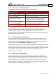
Safety Information Solo Guitar Installation Guide MAN-SOLGUIIG (Ver. 1.403) 1.3.
Solo Guitar Installation Guide 11 MAN-SOLGUIIG (Ver. 1.403) Chapter 2: I ntroduction The Solo Guitar is an integrated solution designed to simply and efficiently connect Elmo’s Guitar servo drive directly to the application. The solution consists of the Guitar together with a convenient connection interface which either eliminates or reduces development time and resources when designing an application’s PCB board.
Solo Guitar Installation Guide Introduction MAN-SOLGUIIG (Ver. 1.403) The Solo Guitar is available in two models: • The Standard Solo Guitar is a basic servo drive, which operates in current, velocity and position modes including Follower and PT & PVT. It operates simultaneously via RS-232 and CAN DS 301, DS 305, DS 402 communications and features a third-generation programming environment.
Introduction Solo Guitar Installation Guide MAN-SOLGUIIG (Ver. 1.403) 2.2.4. Advanced Position Control This relates to the Advanced model only. • Position-based and time-based ECAM mode that supports a non-linear follower mode, in which the motor tracks the master motion using an ECAM table stored in flash memory • Dual (position/velocity) loop 2.2.5.
Solo Guitar Installation Guide Introduction MAN-SOLGUIIG (Ver. 1.403) 2.3. System Architecture Figure 1: Solo Guitar System Block Diagram 2.4. How to Use this Guide In order to install and operate your Elmo Solo Guitar servo drive, you will use this manual in conjunction with a set of Elmo documentation.
Introduction Solo Guitar Installation Guide MAN-SOLGUIIG (Ver. 1.
Solo Guitar Installation Guide 16 MAN-SOLGUIIG (Ver. 1.403) Chapter 3: I nstallation The Solo Guitar must be installed in a suitable environment and properly connected to its voltage supplies and the motor. 3.1. Site Requirements You can guarantee the safe operation of the Solo Guitar by ensuring that it is installed in an appropriate environment.
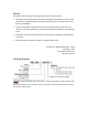
Solo Guitar Installation Guide Installation MAN-SOLGUIIG (Ver. 1.403) It looks like this: The part number at the top gives the type designation as follows: 4. Verify that the Solo Guitar type is the one that you ordered, and ensure that the voltage meets your specific requirements. Note: There are two models of the Solo Guitar: connectors only (for currents of 30 A or less) and wires only (for currents of 35 A or more). On request, the wires model may be ordered for currents of 30 A or less. www.
Installation Solo Guitar Installation Guide MAN-SOLGUIIG (Ver. 1.403) 3.3. Pinouts The Solo Guitar has seven connectors (in the connectors version). 3.3.1. No. Pins Connector Types for the Solo Guitar Type Port Function 9 5.08 mm Pitch (Figure 3) Power + Motor Power 2 5.08 mm Pitch (Figure 4) Power + Motor Power (+seven wires) 14 AWG (M1, M2, M3, VP+, PR) Wires 16 AWG (PE) 4 2.54 mm Pitch J4 Motor (Brake, PTC) 20 2.54 mm Pitch J5 I/O 12 2.54 mm Pitch J1 Communication 12 2.
Installation Solo Guitar Installation Guide MAN-SOLGUIIG (Ver. 1.403) Note: Throughout this chapter there are pairs of diagrams of the Solo Guitar. The diagram on the left is the Solo Guitar with connectors and the diagram on the right shows the product with wires. 3.4. Main Power and Motor Power The Solo Guitar receives power from main and auxiliary supplies and delivers power to the motor. Pin Signal Function 1 VL+ Auxiliary supply input 2 PR Auxiliary supply input return 3 VP+ Pos.
Solo Guitar Installation Guide Installation MAN-SOLGUIIG (Ver. 1.403) Note: When connecting several drives to several motors, all should be wired in the same motor phases and feedback sequences. This will enable the same SimplIQ program to run on all drives. 3.4.1. Connecting Motor Power Connect the M1, M2, M3 and PE pins on the Solo Guitar. The phase connection is arbitrary as the Composer will establish the proper commutation automatically during setup.
Installation Solo Guitar Installation Guide MAN-SOLGUIIG (Ver. 1.403) 3.4.2. Connecting Main Power Power to the Solo Guitar is provided by a 12 to 195 VDC source. A smart control-supply algorithm enables the Solo Guitar to operate with the power supply only, with no need for an auxiliary 24 Volt supply. If backup functionality is required (for storing control parameters in case of power-outs) an additional backup supply can be connected by implementing "diode coupling" to the VL+.
Solo Guitar Installation Guide Installation MAN-SOLGUIIG (Ver. 1.403) 3.4.3. Pin Motor (Brake, PTC) Signal Function J4/1 BRAKE - Brake (-) (coming from the motor) J4/2 BRAKE + Brake (+) (coming from the motor) J4/3 PTC Motor Protection Sensor (coming from the motor) J4/4 PTC Motor Protection Sensor (coming from the motor) Pin Positions Table 3: The Motor Brake and PTC Connector www.elmomc.
Installation Solo Guitar Installation Guide MAN-SOLGUIIG (Ver. 1.403) 3.5. 23 Main Feedback for the Solo Guitar The Main Feedback port is used to transfer feedback data from the motor to the drive.
Solo Guitar Installation Guide Installation MAN-SOLGUIIG (Ver. 1.403) Figure 7: Main Feedback- Incremental Encoder with Digital Hall Sensors Connection Diagram Figure 8: Main Feedback – Interpolated Analog (Sine/Cosine) Encoder Connection Diagram www.elmomc.
Installation Solo Guitar Installation Guide MAN-SOLGUIIG (Ver. 1.403) Figure 9: Main Feedback – Interpolated Analog (Sine/Cosine) Encoder with Digital Hall Sensors Connection Diagram Figure 10: Main Feedback – Resolver Connection Diagram www.elmomc.
Solo Guitar Installation Guide Installation MAN-SOLGUIIG (Ver. 1.403) Figure 11: Main Feedback – Resolver and Digital Hall Sensors Connection Diagram www.elmomc.
Solo Guitar Installation Guide Installation MAN-SOLGUIIG (Ver. 1.403) Figure 12: Main Feedback – Tachometer Feedback with Digital Hall Sensors Connection Diagram for Brushless Motors Figure 13: Main Feedback – Tachometer Feedback Connection Diagram for Brush Motors www.elmomc.
Solo Guitar Installation Guide Installation MAN-SOLGUIIG (Ver. 1.403) Figure 14: Main Feedback – Potentiometer Feedback with Digital Hall Sensors Connection Diagram for Brushless Motors Figure 15: Main Feedback – Potentiometer Feedback Connection Diagram for Brush Motors and Voice Coils www.elmomc.
Solo Guitar Installation Guide Installation MAN-SOLGUIIG (Ver. 1.403) 3.6. Main Buffered Output Port This port provides Differential Buffered Outputs (of the Main Feedback) for another axis.
Solo Guitar Installation Guide Installation MAN-SOLGUIIG (Ver. 1.403) Figure 16: Main Buffered Output Port (Differential Main Feedback Output) – Connection Diagram www.elmomc.
Solo Guitar Installation Guide Installation MAN-SOLGUIIG (Ver. 1.403) 3.7. Auxiliary Feedback (Bi-Directional) When using one of the Auxiliary Feedback options, the relevant functionality of the Auxiliary Feedback's ports are software selected for that option. Refer to the SimplIQ Command Reference Manual for detailed information about Auxiliary Feedback setup. The Auxiliary Feedback connector has two ports: B1 and B2.
Installation Solo Guitar Installation Guide MAN-SOLGUIIG (Ver. 1.403) 3.7.1. Main and Auxiliary Feedback Combinations The Main Feedback is always used in motion control devices whereas Auxiliary Feedback is often, but not always used. The Auxiliary Feedback connector has two ports (B1 and B2).
Installation Solo Guitar Installation Guide MAN-SOLGUIIG (Ver. 1.
Installation Solo Guitar Installation Guide MAN-SOLGUIIG (Ver. 1.
Installation Solo Guitar Installation Guide MAN-SOLGUIIG (Ver. 1.403) 3.7.2. Solo Guitar Auxiliary Feedback – Differential Buffered Encoder Output (YA[4]=4) The Auxiliary Feedback’s B2 port can provide emulated encoder signals to other controllers or drives. This option can be used when: • A Resolver, Analog Encoder or Potentiometer and Tachometer is used as a Main Feedback device. • The Solo Guitar is used as a current amplifier to provide position data to the position controller.
Solo Guitar Installation Guide Installation MAN-SOLGUIIG (Ver. 1.403) Pin Positions Table 6: Emulated Encoder Output on the Auxiliary Feedback Port B2 - Pin Assignments Figure 17: Emulated Encoder Direct Output – Acceptable Connection Diagram www.elmomc.
Installation Solo Guitar Installation Guide MAN-SOLGUIIG (Ver. 1.403) 3.7.3. Auxiliary Feedback – Differential Encoder Input Option (YA[4]=2) The Solo Guitar can be used as a slave by receiving the position data (on Port B1) of the master encoder in Follower or ECAM mode. In this mode, Port B2 provides differential buffered Auxiliary outputs of B1 for the next slave axis in Follower or ECAM mode.
Solo Guitar Installation Guide Installation MAN-SOLGUIIG (Ver. 1.403) Pin Positions Table 7: Differential Auxiliary Encoder Input Option along with Differential Encoder Outputs on Auxiliary Feedback - Pin Assignments www.elmomc.
Solo Guitar Installation Guide Installation MAN-SOLGUIIG (Ver. 1.403) Figure 18: Differential Auxiliary Input Option on Auxiliary Feedback - Connection Diagram www.elmomc.
Installation Solo Guitar Installation Guide MAN-SOLGUIIG (Ver. 1.403) 3.7.4. Auxiliary Feedback – Differential Pulse-and-Direction Input Option (YA[4]=0) This mode is used for input of differential pulse-and-direction position commands on Port B1. In this mode Port B2 provides differential buffered pulse-and-direction outputs of B1 for another axis.
Solo Guitar Installation Guide Installation MAN-SOLGUIIG (Ver. 1.403) Pin Positions Table 8: Pulse-and-Direction Pin Assignments on Auxiliary Feedback Figure 19: Pulse-and-Direction Input Option on Auxiliary Feedback - Connection Diagram www.elmomc.
Installation Solo Guitar Installation Guide MAN-SOLGUIIG (Ver. 1.403) 3.8. I/Os The Solo Guitar has 5 Digital Inputs, 4 Digital Outputs and 1 Analog Input. 3.8.1. Digital Input Each of the pins below can function as an independent input.
Solo Guitar Installation Guide Installation MAN-SOLGUIIG (Ver. 1.403) Figure 20: Digital Input Connection Diagram www.elmomc.
Solo Guitar Installation Guide Installation MAN-SOLGUIIG (Ver. 1.403) 3.8.2. Digital Output Pin (J5) Signal Function 9 VDDIN Digital output supply 10 OUT1 Programmable digital output 1 11 VDDIN Digital output supply 12 OUT2 Programmable digital output 2 13 VDDRET Digital output supply return 14 OUT3 Programmable digital output 3 15 VDDRET Digital output supply return 16 OUT4 Programmable digital output 4 Pin Positions Table 10: Digital Output Pin Assignments www.elmomc.
Solo Guitar Installation Guide Installation MAN-SOLGUIIG (Ver. 1.403) Figure 21: Digital Output Connection Diagram www.elmomc.
Solo Guitar Installation Guide Installation MAN-SOLGUIIG (Ver. 1.403) 3.8.3. Pin (J5) Analog Input Signal Function 18 ANLIN1+ Analog input 1+ 20 ANLIN1- Analog input 1- 17 ANLRET Analog return Pin Positions Table 11: Analog Input Pin Assignments Figure 22: Analog Input with Single-Ended Source www.elmomc.
Installation Solo Guitar Installation Guide MAN-SOLGUIIG (Ver. 1.403) 3.9. Communications The communication interface may differ according to the user’s hardware. The Solo Guitar can communicate using the following options: • RS-232, full duplex • CAN RS-232 communication requires a standard, commercial 3-core null-modem cable connected from the Solo Guitar to a serial interface on the PC. The interface is selected and set up in the Composer software.
Solo Guitar Installation Guide Installation MAN-SOLGUIIG (Ver. 1.403) Figure 23: RS-232 Connection Diagram www.elmomc.
Installation Solo Guitar Installation Guide MAN-SOLGUIIG (Ver. 1.403) 3.9.2. CAN Communication To connect the CAN communication cable 1. Connect the shield to the ground of the host (PC). Usually, this connection is soldered internally inside the connector at the PC end. You can use the drain wire to facilitate connection. 2. Make sure to have a 120-Ω resistor termination at each of the two ends of the network cable. 3. The Solo Guitar’s CAN port is non-isolated.
Solo Guitar Installation Guide Installation MAN-SOLGUIIG (Ver. 1.403) Figure 24: CAN Network Diagram Caution: When installing CAN communication, ensure that each servo drive is allocated a unique ID. Otherwise, the CAN network may hang. www.elmomc.
Solo Guitar Installation Guide Installation MAN-SOLGUIIG (Ver. 1.403) 3.10. Powering Up After the Solo Guitar is connected to its device, it is ready to be powered up. Caution: Before applying power, ensure that the DC supply is within the specified range and that the proper plus-minus connections are in order. 3.11. Initializing the System After the Solo Guitar has been connected and mounted, the system must be set up and initialized.
Solo Guitar Installation Guide Installation MAN-SOLGUIIG (Ver. 1.403) www.elmomc.
Solo Guitar Installation Guide Installation MAN-SOLGUIIG (Ver. 1.403) 3.12.1. How to Use the Charts The charts above are based upon theoretical worst-case conditions. Actual test results show 30% to 50% better power dissipation. To determine if your application needs a heatsink: 1. Allow maximum heatsink temperature to be 80 °C or less. 2. Determine the ambient operating temperature of the Solo Guitar. 3.
Solo Guitar Installation Guide 54 MAN-SOLGUIIG (Ver. 1.403) Chapter 4: Technical Specifications This chapter provides detailed technical information regarding the Solo Guitar. This includes its dimensions, power ratings, the environmental conditions under which it can be used, the standards to which it complies and other specifications. 4.1. Features The Solo Guitar's features determine how it controls motion, as well as how it processes host commands, feedback and other input. 4.1.1.
Solo Guitar Installation Guide Technical Specifications MAN-SOLGUIIG (Ver. 1.403) 4.1.5.
Solo Guitar Installation Guide Technical Specifications MAN-SOLGUIIG (Ver. 1.403) 4.1.7. Built-In Protection • Software error handling • Abort (hard stops and soft stops) • Status reporting • Protection against: Shorts between motor power outputs Shorts between motor power outputs and power input/return Failure of internal power supplies Over-heating Continuous temperature measurement.
Solo Guitar Installation Guide Technical Specifications MAN-SOLGUIIG (Ver. 1.403) 4.2. Solo Guitar Dimensions Figure 25: Solo Guitar Dimensions www.elmomc.
Technical Specifications Solo Guitar Installation Guide 58 MAN-SOLGUIIG (Ver. 1.403) 4.3.
Technical Specifications Solo Guitar Installation Guide MAN-SOLGUIIG (Ver. 1.403) 4.4.
Technical Specifications Solo Guitar Installation Guide MAN-SOLGUIIG (Ver. 1.403) 4.5.2.
Technical Specifications Solo Guitar Installation Guide MAN-SOLGUIIG (Ver. 1.403) 4.5.3. Position Loop Feature Details Controller type “1-2-4” PIP Position command options • Software • Pulse and Direction • Analog Potentiometer Position loop bandwidth < 80 Hz Position sampling time 280 to 400 µsec (4x current loop sample time) Position sampling rate Up to 4 kHz; default 2.75 kHz 4.6. Feedbacks 4.6.1. Feedback Supply Voltage The Solo Guitar has two feedback ports (Main and Auxiliary).
Technical Specifications Solo Guitar Installation Guide MAN-SOLGUIIG (Ver. 1.403) 4.6.2. Main Feedback Options The Solo Guitar can receive and process feedback input from diverse types of devices. 4.6.2.1.
Technical Specifications Solo Guitar Installation Guide MAN-SOLGUIIG (Ver. 1.403) 4.6.2.2. Digital Halls Feature Details Halls inputs • HA, HB, HC. • Single ended inputs • Built in hysteresis of 1 V for noise immunity Input voltage Nominal operating range: 0 V < VIn_Hall < 5 V Maximum absolute: -1 V < VIn_Hall < 15 V High level input voltage: V InHigh > 2.
Technical Specifications Solo Guitar Installation Guide MAN-SOLGUIIG (Ver. 1.403) 4.6.2.4. Resolver Feature Details Resolver format • Sine/Cosine • Differential Input resistance Differential 2.49 kΩ Resolution Programmable: 10 to 15 bits Maximum electrical frequency (RPS) 512 revolutions/sec Resolver transfer ratio 0.
Technical Specifications Solo Guitar Installation Guide MAN-SOLGUIIG (Ver. 1.403) 4.6.2.6. Potentiometer Feature Details Potentiometer Format Single-ended Operating Voltage Range 0 to 5 V supplied by the Solo Guitar Potentiometer Resistance 100 Ω to 1 kΩ … above this range, linearity is affected detrimentally Input Resistance 100 kΩ Resolution 14 bit 4.6.3.
Technical Specifications Solo Guitar Installation Guide MAN-SOLGUIIG (Ver. 1.403) 4.6.4. Auxiliary Feedback Port (output mode YA[4]= 4) Feature Details Emulated output • A, B, Index • Differential Output current capability • Maximum output current: IOH (max) = 2 mA • High level output voltage: VOH > 3.0 V • Minimum output current: IOL = 2 mA • Low level output voltage: VOL < 0.
Technical Specifications Solo Guitar Installation Guide MAN-SOLGUIIG (Ver. 1.403) 4.6.5. Auxiliary Feedback Port (input mode YA[4]= 2, 0) Feature Details Encoder input, pulse and direction input Input voltage • A, B, Index • Differential VIn Low: 0 V < VIL < 0.8 V VIn High: 2 V < VIH < 5 V Maximum absolute voltage: 0 < VIn < 5.
Technical Specifications Solo Guitar Installation Guide MAN-SOLGUIIG (Ver. 1.403) 4.7. I/Os The Solo Guitar has: • 5 Digital Inputs • 4 Digital Outputs • 1 Analog Input 4.7.1. Digital Input Interfaces Feature Details Type of input Optically isolated Input current for all inputs Rin=3.43K, Iin = 1.2 mA @ Vin = 5 V Rin=3.43K, Iin = 6.
Technical Specifications Solo Guitar Installation Guide MAN-SOLGUIIG (Ver. 1.403) 4.7.2. Powerful Digital Output Interface Feature Type of output Details • Optically isolated • Powerful Source capability VDD Supply Range 15 V to 30 V Max. output current Iout (max) Iout1 (max) ≤ 500 mA VOH VDD≥VOH ≥ VDD-(Ix0.15) VOL VOL ≤ 1 V RL External RL must be selected to limit output current. Iout2, 3, 4 (max) ≤ 250 mA RL=VDD-Ix0.
Technical Specifications Solo Guitar Installation Guide MAN-SOLGUIIG (Ver. 1.403) 4.7.3. Opto Digital Output Interface Feature Type of output Details • Optically isolated • Open emitter VDD Supply Range 2.5 V to 30 V Max. output current Iout (max) Iout (max) ≤ 8 mA VOL VOL ≤ 0.3 V RL External RL must be selected to limit output current.
Technical Specifications Solo Guitar Installation Guide MAN-SOLGUIIG (Ver. 1.403) 4.7.4. Brake The brake can be controlled by Digital Output 1. Digital Output 1 should be set to Brake. Feature Details Rated voltage 24 V +10% Rated current 0.5 A Input power 12 W 4.7.5. Analog Input Feature Details Maximum operating differential voltage ± 10 V Maximum absolute differential input voltage ± 16 V Differential input resistance 3.74 kΩ Analog input command resolution 14-bit 4.8.
Technical Specifications Solo Guitar Installation Guide MAN-SOLGUIIG (Ver. 1.403) 4.9. Pulse-Width Modulation (PWM) Feature Details PWM resolution 12-bit PWM switching frequency on the load 2/Ts (factory default 22 kHz on the motor) 4.10. Compliance with Standards Specification Details Quality Assurance ISO 9001:2008 Quality Management Design Approved IEC/EN 61800-5-1, Safety Printed wiring for electronic equipment (clearance, creepage, spacing, conductors sizing, etc.
Technical Specifications Solo Guitar Installation Guide MAN-SOLGUIIG (Ver. 1.