
Installation Guide User guide

Solo Guitar Installation Guide Installation
MAN-SOLGUIIG (Ver. 1.403)
www.elmomc.com
49
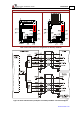
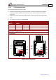
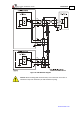
3.9.2. CAN Communication
To connect the CAN communication cable
1. Connect the shield to the ground of the host (PC). Usually, this connection is soldered
internally inside the connector at the PC end. You can use the drain wire to facilitate
connection.
2. Make sure to have a 120-Ω resistor termination at each of the two ends of the network
cable.
3. The Solo Guitar’s CAN port is non-isolated.
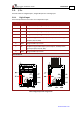
Pin (J1)
CANIN
Pin (J1)
CANOUT
Signal
Function
1 5 CAN_L CAN_L busline (dominant low)
2 6 CAN_H CAN_H busline (dominant high)
3 7 CAN_GND CAN ground
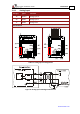
Pin positions in diagram below.
Pin Positions
Table 13: CAN - Pin Assignments