Solo Trombone Digital Servo Drive Installation Guide July 2014 (Ver. 1.203) www.elmomc.
Notice This guide is delivered subject to the following conditions and restrictions: • This guide contains proprietary information belonging to Elmo Motion Control Ltd. Such information is supplied solely for the purpose of assisting users of the Solo Trombone servo drive in its installation. • The text and graphics included in this manual are for the purpose of illustration and reference only. The specifications on which they are based are subject to change without notice.
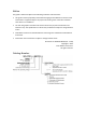
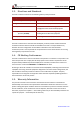
Revision History Version Details 1.0 Initial release 1.1 Update to site requirements. Sections 4.3 and 4.3.1: Auxiliary Supply Voltage range: 18 V to 30 V. 1.2 September 2012 Change the overvoltage in 800 V mode, Pin layout, UL recognition, and further optional versions added Updated the Section 1.3: Directives and Standards and Section 4.11 (Compliance with Standards). “Metronome” was replaced by the “Composer” software. 1.
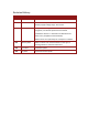
Elmo Worldwide Head Office Elmo Motion Control Ltd. 60 Amal St., P.O. Box 3078, Petach Tikva 49516 Israel Tel: +972 (3) 929-2300 • Fax: +972 (3) 929-2322 • info-il@elmomc.com North America Elmo Motion Control Inc. 42 Technology Way, Nashua, NH 03060 USA Tel: +1 (603) 821-9979 • Fax: +1 (603) 821-9943 • info-us@elmomc.com Europe Elmo Motion Control GmbH Hermann-Schwer-Strasse 3, 78048 VS-Villingen Germany Tel: +49 (0) 7721-944 7120 • Fax: +49 (0) 7721-944 7130 • info-de@elmomc.
Solo Trombone Installation Guide MAN-SOLTROIG (Ver. 1.203) Table of Contents Chapter 1: 1.1. 1.2. 1.3. 1.4. 1.5. Warnings......................................................................................................................... 9 Cautions .......................................................................................................................... 9 Directives and Standards ..............................................................................................
Solo Trombone Installation Guide Table of Contents MAN-SOLTROIG (Ver. 1.203) 3.5.3. 3.5.4. 3.6. 3.7. 3.8. Auxiliary Feedback - Differential Encoder Input Option (YA[4]=2) ................ 45 Auxiliary Feedback – Differential Pulse-and-Direction Input Option (YA[4]=0) ....................................................................................................................... 48 3.5.5. I/Os ........................................................................................................
Solo Trombone Installation Guide Table of Contents MAN-SOLTROIG (Ver. 1.203) 4.6.2.6. Tachometer................................................................................... 75 4.6.2.7. Potentiometer .............................................................................. 75 4.6.3. Main Encoder Buffered Output ..................................................................... 76 4.6.4. Auxiliary Feedback Port (output mode YA[4]= 4) .......................................... 77 4.6.5.
Solo Trombone Installation Guide 8 MAN-SOLTROIG (Ver. 1.203) Chapter 1: Safety I nform ation In order to operate the Solo Trombone servo drive safely, it is imperative that you implement the safety procedures included in this installation guide. This information is provided to protect you and to keep your work area safe when operating the Solo Trombone and accompanying equipment. Please read this chapter carefully, before you begin the installation process.
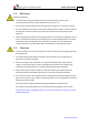
Solo Trombone Installation Guide Safety Information MAN-SOLTROIG (Ver. 1.203) 1.1. Warnings Employ the following: • To avoid electric arcing and hazards to personnel and electrical contacts, never connect/disconnect the servo drive while the power source is on. • Disconnect the Solo Trombone from all voltage sources before it is opened for servicing. • The Solo Trombone servo drive contains grounding conduits for electric current protection.
Solo Trombone Installation Guide Safety Information MAN-SOLTROIG (Ver. 1.203) 1.3.
Solo Trombone Installation Guide 11 MAN-SOLTROIG (Ver. 1.203) Chapter 2: I ntroduction The Solo Trombone is an integrated solution designed to simply and efficiently connect Elmo’s Trombone servo drive directly to the application. The solution consists of the Trombone together with a convenient connection interface which either eliminates or reduces development time and resources when designing an application’s PCB board.
Solo Trombone Installation Guide Introduction MAN-SOLTROIG (Ver. 1.203) The Solo Trombone is available in two versions: • The Standard Solo Trombone is a basic servo drive which operates in current, velocity, and position modes including Follower and PT & PVT. It operates simultaneously via RS-232 and CANopen DS 301, DS 305, DS 402 communications and features a third-generation programming environment. (The catalog number starts SOL-TRO but is not followed by an A.
Introduction Solo Trombone Installation Guide MAN-SOLTROIG (Ver. 1.203) • PT and PVT motion modes • Fast output compare (OC) 2.2.4. Advanced Position Control This relates to the Advanced model only. • Position-based and time-based ECAM mode that supports a non-linear follower mode, in which the motor tracks the master motion using an ECAM table stored in flash memory • Dual (position/velocity) loop 2.2.5.
Introduction Solo Trombone Installation Guide MAN-SOLTROIG (Ver. 1.203) 2.2.7.
Solo Trombone Installation Guide Introduction MAN-SOLTROIG (Ver. 1.203) 2.4. How to Use this Guide In order to install and operate the Solo Trombone servo drive, use this manual in conjunction with a set of Elmo documentation.
Solo Trombone Installation Guide 16 MAN-SOLTROIG (Ver. 1.203) Chapter 3: I nstallation Warning: The Solo Trombone must be: 3.1. • installed in a suitable environment and properly connected to its voltage supplies and the motor. • mounted and confined within a metal enclosure. Before You Begin 3.1.1. Site Requirements You can guarantee the safe operation of the Solo Trombone by ensuring that it is installed in an appropriate environment.
Installation Solo Trombone Installation Guide MAN-SOLTROIG (Ver. 1.203) 3.2. Unpacking the Drive Components Before you begin working with the Solo Trombone, verify that you have all of its components, as follows: • The Solo Trombone servo drive • The Composer software and software manual The Solo Trombone is shipped in a cardboard box with styrofoam protection. To unpack the Solo Trombone 1. Carefully remove the servo drive from the box and the Styrofoam. 2.
Installation Solo Trombone Installation Guide MAN-SOLTROIG (Ver. 1.203) 3.3. Pinouts The Solo Trombone has nine connectors. 3.3.1. Connector Types The Solo Trombone has the following types of connectors: No. Pins Type Port Function 2 5.08 mm Pitch J18 Aux connection 7 8 mm Pitch J14 Power + Motor Power 4 2.54 mm Pitch J5 Motor (Brake, PTC) 20 2.54 mm Pitch J7 I/O 3 2.54 mm Pitch J22 Not in use 12 2.54 mm Pitch J3 Communication 16 2.54 mm Pitch J10 Main Feedback 8 2.
Installation Solo Trombone Installation Guide MAN-SOLTROIG (Ver. 1.203) 3.3.2. Main Power and Motor Power The Solo Trombone receives power from main and auxiliary supplies and delivers power to the motor. 3.3.2.1. Pin S Type Drives Function Cable Auxiliary 24 VDC Control Supply VL- Neg. Aux. input Control Power VL+ Pos. Aux. input Control Power VP+ Pos. Power input DC Power VN- Neg.
Installation Solo Trombone Installation Guide MAN-SOLTROIG (Ver. 1.203) 3.3.2.2. Pin Non-S 400 VDC Type Drives Function Cable Not used VL- N.C. VL+ N.C. Power VP+ Pos. Power input DC Power VN- Neg. Power input DC Power PE Protective earth DC Power Motor AC DC PE Protective earth Motor Motor M1 Motor phase Motor N.
Solo Trombone Installation Guide Installation MAN-SOLTROIG (Ver. 1.203) 3.3.3. Connecting Motor Power Connect the M1, M2, M3 and PE pins on the Solo Trombone. The phase connection is arbitrary, as the Composer will establish the proper commutation automatically during setup. However, if you plan to copy the setup to other drives, then the phase order on all copy drives must be the same. Figure 2: AC Motor Power Connection Diagram 3.3.3.1.
Installation Solo Trombone Installation Guide MAN-SOLTROIG (Ver. 1.203) 3.3.3.2. Direct-to-Mains Power Source (Non-Isolated Rectifier) This section relates to the configuration of the power supply and drive, which are directly connected to the Mains. Note for connecting the non-isolated DC power supply: 1. For best immunity, it is highly recommended to use twisted cables for the DC power supply cable. A 3-wire shielded cable should be used.
Installation Solo Trombone Installation Guide MAN-SOLTROIG (Ver. 1.203) 3.3.3.2.b Single-Phase Direct-to-Mains Connection Topology Figure 4: Non-Isolated Single-Phase Connection Topology The Power Supply is connected directly to the Mains AC line. Warning: • Do not connect VN- to PE. In a direct-to-mains connection the VN- must not be connected to the PE. Connecting the VN- to the PE will cause irreparable damage to the system.
Solo Trombone Installation Guide Installation MAN-SOLTROIG (Ver. 1.203) 3.3.3.2.c Multiple Connections Topology In a multi-axis application, it is likely that a single power supply can feed several drives in parallel. This topology is rather economic, by reducing the number of power supplies and wiring, but most importantly, it utilizes an "energy-sharing" environment among all the drives that are sharing the same DC bus network.
Solo Trombone Installation Guide Installation MAN-SOLTROIG (Ver. 1.203) 3.3.3.3. Battery Power Supply Figure 6: Battery Connection Topology Caution: When using batteries, it is recommended to connect the negative pole to the PE. When doing so, the charger of the battery must be isolated from the mains by an isolation transformer. www.elmomc.
Installation Solo Trombone Installation Guide MAN-SOLTROIG (Ver. 1.203) 3.3.4. Connecting the Control and Backup Supply (24 V) In a non-S type Solo Trombone drive (a drive without the suffix S in its part number), a “smart” control-supply algorithm enables the Solo Trombone to operate with the main power supply only, with no need for an auxiliary supply voltage for supplying the drive's logic section. Note that in such model there is no backup ability at all.
Solo Trombone Installation Guide Installation MAN-SOLTROIG (Ver. 1.203) 3.3.5. Motor (Brake, PTC) Pin (J5) Signal Function 1 BRAKE - Brake (-) (coming from the motor) 2 BRAKE + Brake (+) (coming from the motor) 3 PTC Motor Protection Sensor (coming from the motor) 4 PTC Motor Protection Sensor (coming from the motor) Pin Positions Table 4: The Motor Brake and PTC Connector www.elmomc.
Installation Solo Trombone Installation Guide MAN-SOLTROIG (Ver. 1.203) 3.3.6. 28 Main Feedback The main feedback cable is used to transfer feedback data from the motor to the drive.
Installation Solo Trombone Installation Guide MAN-SOLTROIG (Ver. 1.
Solo Trombone Installation Guide Installation MAN-SOLTROIG (Ver. 1.203) Figure 8: Main Feedback – Incremental Encoder with Digital Hall Sensors Connection Diagram Figure 9: Main Feedback – Interpolated Analog (Sine/Cosine) Encoder Connection Diagram www.elmomc.
Installation Solo Trombone Installation Guide MAN-SOLTROIG (Ver. 1.203) Figure 10: Main Feedback – Interpolated Analog (Sine/Cosine) Encoder with Digital Hall Sensors Connection Diagram Figure 11: Main Feedback – Resolver Connection Diagram www.elmomc.
Solo Trombone Installation Guide Installation MAN-SOLTROIG (Ver. 1.203) Figure 12: Main Feedback – Tachometer Feedback with Digital Hall Sensors Connection Diagram for Brushless Motors Figure 13: Main Feedback – Tachometer Feedback Connection Diagram for Brush Motors www.elmomc.
Solo Trombone Installation Guide Installation MAN-SOLTROIG (Ver. 1.203) Figure 14: Main Feedback – Potentiometer Feedback with Digital Hall Sensors Connection Diagram for Brushless Motors Figure 15: Main Feedback – Potentiometer Feedback Connection Diagram for Brush Motors and Voice Coils www.elmomc.
Solo Trombone Installation Guide Installation MAN-SOLTROIG (Ver. 1.203) Figure 16: Main Feedback – Stegmann Feedback Connection Diagram Figure 17: Main Feedback – Heidenhain Feedback Connection Diagram www.elmomc.
Solo Trombone Installation Guide Installation MAN-SOLTROIG (Ver. 1.203) Figure 18: Main Feedback – Panasonic Feedback Connection Diagram www.elmomc.
Solo Trombone Installation Guide Installation MAN-SOLTROIG (Ver. 1.203) 3.4. Main Buffered Output Port This port provides Differential Buffered Outputs (of the Main Feedback) for another axis.
Solo Trombone Installation Guide Installation MAN-SOLTROIG (Ver. 1.203) Figure 19: Main Buffered Output Port (Differential Main Feedback Output) – Connection Diagram www.elmomc.
Solo Trombone Installation Guide Installation MAN-SOLTROIG (Ver. 1.203) 3.5. Auxiliary Feedback (Bi-Directional) When using one of the Auxiliary Feedback options, the relevant functionality of the Auxiliary Feedback's ports are software selected for that option. Refer to the SimplIQ Command Reference Manual for detailed information about Auxiliary Feedback setup. The Auxiliary Feedback connector has two ports: B1 and B2. • Port B1 has three pairs of differential buffered inputs.
Installation Solo Trombone Installation Guide MAN-SOLTROIG (Ver. 1.203) 3.5.1. Main and Auxiliary Feedback Combinations The Main Feedback is always used in motion control devices, whereas the Auxiliary Feedback is often, but not always used. The Auxiliary Feedback connector on the Solo Trombone, AUX. FEEDBACK, has two ports, Port B1 and Port B2.
Installation Solo Trombone Installation Guide MAN-SOLTROIG (Ver. 1.
Installation Solo Trombone Installation Guide MAN-SOLTROIG (Ver. 1.
Installation Solo Trombone Installation Guide MAN-SOLTROIG (Ver. 1.203) 3.5.2. Solo Trombone Auxiliary Feedback – Differential Buffered Encoder Output (YA[4]=4) The Auxiliary Feedback’s B2 port can provide emulated encoder signals to other controllers or drives. This option can be used when: • A Resolver, Interpolated Analog Encoder, Absolute Encoder (Stegmann, Heidenhain or Panasonic), or Potentiometer and Tachometer is used as a Main Feedback device.
Solo Trombone Installation Guide Installation MAN-SOLTROIG (Ver. 1.203) Pin Positions Table 8: Emulated Encoder Output on the Auxiliary Feedback Port B2 - Pin Assignments www.elmomc.
Solo Trombone Installation Guide Installation MAN-SOLTROIG (Ver. 1.203) Figure 20: Emulated Encoder Direct Output – Acceptable Connection Diagram www.elmomc.
Installation Solo Trombone Installation Guide MAN-SOLTROIG (Ver. 1.203) 3.5.3. Auxiliary Feedback - Differential Encoder Input Option (YA[4]=2) The Solo Trombone can be used as a slave by receiving the position data (on Port B1) of the master encoder in Follower or ECAM mode. In this mode, Port B2 provides differential buffered Auxiliary outputs of B1 for the next slave axis in Follower or ECAM mode.
Solo Trombone Installation Guide Installation MAN-SOLTROIG (Ver. 1.203) Pin Positions Table 9: Differential Auxiliary Encoder Input Option along with Differential Encoder Outputs on Auxiliary Feedback - Pin Assignments www.elmomc.
Solo Trombone Installation Guide Installation MAN-SOLTROIG (Ver. 1.203) Figure 21: Differential Auxiliary Input Option on Auxiliary Feedback - Connection Diagram www.elmomc.
Solo Trombone Installation Guide Installation MAN-SOLTROIG (Ver. 1.203) 3.5.4. Auxiliary Feedback – Differential Pulse-and-Direction Input Option (YA[4]=0) This mode is used for input of differential pulse-and-direction position commands on Port B1. In this mode Port B2 provides differential buffered pulse-and-direction outputs of B1 for another axis.
Solo Trombone Installation Guide Installation MAN-SOLTROIG (Ver. 1.203) Pin Positions Table 10: Pulse-and-Direction Pin Assignments on Auxiliary Feedback www.elmomc.
Solo Trombone Installation Guide Installation MAN-SOLTROIG (Ver. 1.203) Figure 22: Pulse-and-Direction Input Option on Auxiliary Feedback - Connection Diagram www.elmomc.
Installation Solo Trombone Installation Guide MAN-SOLTROIG (Ver. 1.203) 3.5.5. I/Os The Solo Trombone has 6 Digital Inputs, 4 Digital Outputs and 1 Analog Input. 3.5.5.1. Digital Input Each of the pins below can function as an independent input.
Solo Trombone Installation Guide Installation MAN-SOLTROIG (Ver. 1.203) Figure 23: Digital Input Connection Diagram www.elmomc.
Solo Trombone Installation Guide Installation MAN-SOLTROIG (Ver. 1.203) 3.5.6. Digital Output Pin (J7) Signal Function 9 VDDIN Digital output supply 10 OUT1 Programmable digital output 1 11 VDDIN Digital output supply 12 OUT2 Programmable digital output 2 13 VDDRET Digital output supply return 14 OUT3 Programmable digital output 3 15 VDDRET Digital output supply return 16 OUT4 Programmable digital output 4 Pin Positions Table 12: Digital Output Pin Assignments www.elmomc.
Solo Trombone Installation Guide Installation MAN-SOLTROIG (Ver. 1.203) Figure 24: Digital Output Connection Diagram www.elmomc.
Solo Trombone Installation Guide Installation MAN-SOLTROIG (Ver. 1.203) 3.5.7. Pin (J7) Analog Input Signal Function 18 ANLIN1+ Analog input 1+ 20 ANLIN1- Analog input 1- 17 ANLRET Analog return Pin Positions Table 13: Analog Input Pin Assignments Figure 25: Analog Input with Single-Ended Source www.elmomc.
Solo Trombone Installation Guide Installation MAN-SOLTROIG (Ver. 1.203) 3.5.8. Communication The communication interface may differ according to the user’s hardware. The Solo Trombone can communicate using the following options: • RS-232, full duplex • CAN RS-232 communication requires a standard, commercial 3-core null-modem cable connected from the Solo Trombone to a serial interface on the PC. The interface is selected and set up in the Composer software.
Solo Trombone Installation Guide Installation MAN-SOLTROIG (Ver. 1.203) Figure 26: RS-232 Connection Diagram 3.5.8.2. CAN Communication To connect the CAN communication cable 1. Connect the shield to the ground of the host (PC). Usually, this connection is soldered internally inside the connector at the PC end. You can use the drain wire to facilitate connection. 2. Make sure to have a 120-Ω resistor termination at each of the two ends of the network cable. 3.
Installation Solo Trombone Installation Guide MAN-SOLTROIG (Ver. 1.203) Pin (J3) Pin (J3) CANIN CANOUT Signal Function 1 5 CAN_L CAN_L busline (dominant low) 2 6 CAN_H CAN_H busline (dominant high) 3 7 CAN_GND CAN ground Pin Positions Table 15: CAN - Pin Assignments www.elmomc.
Installation Solo Trombone Installation Guide MAN-SOLTROIG (Ver. 1.203) Caution: When installing the CAN communications, ensure that each servo drive is allocated a unique ID. Otherwise, the CAN network may hang. Figure 27: CAN - Connection Diagram www.elmomc.
Installation Solo Trombone Installation Guide MAN-SOLTROIG (Ver. 1.203) 3.6. Powering Up After the Solo Trombone has been mounted, check that the cables are intact. The Solo Trombone servo drive is then ready to be powered up. Caution: Before applying power, ensure that the DC supply is within the range specified for your specific type of Solo Trombone and that the proper plus-minus connections are in order. 3.7.
Solo Trombone Installation Guide Installation MAN-SOLTROIG (Ver. 1.203) 3.8.2. Heat Dissipation Data Heat Dissipation is shown graphically below: Figure 28: Dissipation versus Current Graph for 560 and 680 VDC Figure 29: Dissipation versus Current Graph for 330 VDC www.elmomc.
Installation Solo Trombone Installation Guide MAN-SOLTROIG (Ver. 1.203) 3.8.3. How to Use the Charts The power dissipation in the chart includes the losses of the rectifying bridge. Regarding Figure 28 and Figure 29, the following should be noted: DC Bus Voltage (VDC) Rectified Voltage (VAC) 560 3X400 680 3X480 330 3X230 The charts above are based upon theoretical worst-case conditions. Actual test results show 30% to 50% better power dissipation.
Solo Trombone Installation Guide 63 MAN-SOLTROIG (Ver. 1.203) Chapter 4: Technical Specifications This chapter provides detailed technical information regarding the Solo Trombone. This includes its dimensions, power ratings, the environmental conditions under which it can be used, the standards to which it complies and other specifications. 4.1. Features The Solo Trombone's features determine how it controls motion, as well as how it processes host commands, feedback and other input. 4.1.1.
Solo Trombone Installation Guide Technical Specifications MAN-SOLTROIG (Ver. 1.203) 4.1.5.
Solo Trombone Installation Guide Technical Specifications MAN-SOLTROIG (Ver. 1.203) • Buffered and differential outputs of the main encoder with up to 5 MHz pulses • Buffered and differential outputs of the auxiliary encoder • Emulated Buffered and differential outputs of resolver or analog encoder • Pulse and Direction inputs (Differential) • PWM current command output for torque and velocity 4.1.7.
Solo Trombone Installation Guide Technical Specifications MAN-SOLTROIG (Ver. 1.203) 4.1.10. Automatic Procedures • Commutation alignment • Phase sequencing • Current loop offset adjustment • Current loop gain tuning • Current gain scheduling • Velocity loop offset adjustment • Velocity gain tuning • Velocity gain scheduling • Position gain tuning 4.2. Solo Trombone Dimensions www.elmomc.
Technical Specifications Solo Trombone Installation Guide 67 MAN-SOLTROIG (Ver. 1.203) 4.3.
Technical Specifications Solo Trombone Installation Guide MAN-SOLTROIG (Ver. 1.203) 4.3.1. Auxiliary Supply This table applies only to the models with an S suffix. See page 17 for further details on the part number. Feature Details Auxiliary power supply Isolated DC source only Auxiliary supply input voltage 18 to 30 VDC Auxiliary supply input power < 8 VA (this includes the 5 V/2x200 mA load for the main and auxiliary encoders) Note: An S-type drive will not operate unless it has the Aux.
Technical Specifications Solo Trombone Installation Guide MAN-SOLTROIG (Ver. 1.203) 4.5. Control Specifications 4.5.1.
Solo Trombone Installation Guide Technical Specifications MAN-SOLTROIG (Ver. 1.203) 4.5.2.
Technical Specifications Solo Trombone Installation Guide MAN-SOLTROIG (Ver. 1.203) 4.5.3. Position Loop Feature Details Controller type “1-2-4” PIP Position command options • Software • Pulse and Direction • Analog Potentiometer Position loop bandwidth < 80 Hz Position sampling time 280 to 400 µsec (4x current loop sample time) Position sampling rate Up to 4 kHz; default 2.75 kHz 4.6. Feedbacks 4.6.1.
Technical Specifications Solo Trombone Installation Guide MAN-SOLTROIG (Ver. 1.203) 4.6.2. Main Feedback Options The Solo Trombone can receive and process feedback input from diverse types of devices. 4.6.2.1.
Solo Trombone Installation Guide Technical Specifications MAN-SOLTROIG (Ver. 1.203) 4.6.2.2. Digital Halls Feature Details Halls inputs • HA, HB, HC. • Single ended inputs • Built in hysteresis of 1 V for noise immunity Input voltage Nominal operating range: 0 V < VIn_Hall < 5 V Maximum absolute: -1 V < VIn_Hall < 15 V High level input voltage: V InHigh > 2.
Technical Specifications Solo Trombone Installation Guide MAN-SOLTROIG (Ver. 1.203) 4.6.2.4. Interpolated Analog (Sine/Cosine) Encoder Feature Details Analog encoder format Sine and Cosine signals Analog input signal level • Offset voltage: 2.2 V to 2.
Solo Trombone Installation Guide Technical Specifications MAN-SOLTROIG (Ver. 1.203) 4.6.2.6.
Solo Trombone Installation Guide Technical Specifications MAN-SOLTROIG (Ver. 1.203) 4.6.3.
Technical Specifications Solo Trombone Installation Guide MAN-SOLTROIG (Ver. 1.203) 4.6.4. Auxiliary Feedback Port (output mode YA[4]= 4) Feature Details • A, B, Index Emulated output • Differential outputs Output current capability Maximum output current: IOH (max) = 2 mA High level output voltage: VOH > 3.0 V Minimum output current: IOL = 2 mA Low level output voltage: VOL < 0.
Technical Specifications Solo Trombone Installation Guide MAN-SOLTROIG (Ver. 1.203) 4.6.5. Auxiliary Feedback Port (input mode YA[4]= 2, 0) Feature Details Encoder input, pulse and direction input Input voltage • A, B, Index • Differential VIn Low: 0 V < VIL < 0.8 V VIn High: 2 V < VIH < 5 V Maximum absolute voltage: 0 < VIn < 5.
Solo Trombone Installation Guide Technical Specifications MAN-SOLTROIG (Ver. 1.203) 4.7. I/Os The Solo Trombone has • 6 Digital Inputs • 4 Digital Outputs • 1 Analog Input 4.7.1. Digital Input Interfaces Feature Details Type of input Optically isolated Input current for all inputs Rin=3.43K, Iin = 1.
Technical Specifications Solo Trombone Installation Guide MAN-SOLTROIG (Ver. 1.203) 4.7.2. Powerful Digital Output Interface Feature Type of output Details • Optically isolated • Powerful Sink/Source capability Maximum supply output (Vdd) 30 V Max. output current Iout (max) (Vout = Low) Iout (max) ≤ 250 mA VOH at maximum output voltage VDO ≥ VOH ≥ VDO-1.25 VOH @ 250 mA Source mode VOL at maximum output voltage 0 V ≤ VOL ≤ 1.
Technical Specifications Solo Trombone Installation Guide MAN-SOLTROIG (Ver. 1.203) 4.7.3. Analog Input Feature Details Maximum operating differential voltage ± 10 V Maximum absolute differential input voltage ± 16 V Differential input resistance 3.74 kΩ Analog input command resolution 14-bit 4.8. Communications Specification Details RS-232 Signals: • RxD , TxD , Gnd • Full duplex, serial communication for setup and control. • Baud Rate of 9,600 to 57,600 bit/sec.
Technical Specifications Solo Trombone Installation Guide MAN-SOLTROIG (Ver. 1.203) 4.11. Compliance with Standards Specification Details Quality Assurance ISO 9001:2008 Quality Management Design Approved IEC/EN 61800-5-1, Safety Printed wiring for electronic equipment (clearance, creepage, spacing, conductors sizing, etc.) MIL-HDBK- 217F Reliability prediction of electronic equipment (rating, de-rating, stress, etc.
Technical Specifications Solo Trombone Installation Guide MAN-SOLTROIG (Ver. 1.