
Installation Guide User Manual


Solo Trombone Installation Guide Installation
MAN-SOLTROIG (Ver. 1.203)
www.elmomc.com
28
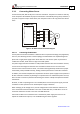
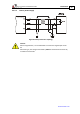
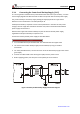
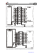
3.3.6. Main Feedback
The main feedback cable is used to transfer feedback data from the motor to the drive.
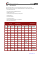
The Solo Trombone can accept any one the following devices as a main feedback mechanism:
• Incremental encoder only
• Incremental encoder with digital Hall sensors
• Digital Hall sensors only
• Interpolated Analog (Sine/Cosine) encoder (option)
• Resolver (option)
• Tachometer (option)
• Potentiometer (option)
• Absolute Encoder (Heidenhain 2.1 or Stegmann)
• Panasonic absolute encoder
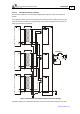
Incremental
Encoder
Interpolated
Analog Encoder
Resolver Tachometer and
Potentiometer
SOL-ARTROXX/YYY_ SOL -ARTROXX/YYYI SOL -ARTROXX/YYYR SOL -ARTROXX/YYYT
Pin
(J10)
Signal Function Signal Function Signal Function Signal Function
14 HC Hall sensor C
input
HC Hall sensor C
input
NC - HC Hall sensor C
input
12 HA Hall sensor A
input
HA Hall sensor A
input
NC - HA Hall sensor A
input
15 SUPRET Supply return SUPRET Supply return SUPRET Supply return SUPRET Supply return
2 +5V Encoder/Hall
+5V supply
+5V
Encoder/Hall +5V
supply
+5V Encoder/Hall +5V
supply
+5V Encoder/Hall
+5V supply
4 CHA- Channel A
complement
A- Sine A
complement
S3 Sine A
complement
Tac 1- Tacho Input 1
Neg. (20 V max)
3 CHA Channel A A+ Sine A S1 Sine A Tac 1+ Tacho Input 1
Pos. (20 V max)
8 INDEX- Index
complement
R- Reference
complement
R2 Vref complement
f= 1/TS, 50 mA
Maximum
NC -
7 INDEX Index R+ Reference R1 Vref f=1/TS,
50 mA Max.
POT Potentiometer
Input
1 SUPRET Supply return SUPRET Supply return SUPRET Supply return SUPRET Supply return
11 HB Hall sensor B
input
HB Hall sensor B
input
NC - HB Hall sensor B
input
6 CHB- Channel B
complement
B- Cosine B
complement
S4 Cosine B
complement
Tac 2- Tacho Input 2
Neg. (50 V max)
5 CHB Channel B B+ Cosine B S2 Cosine B Tac 2+ Tacho Input 2
Pos. (50 V max)
Table 5: Main Feedback Cable Pin Assignments (Part A)