Trio Installation Guide September 2008 (Ver. 1.0) www.elmomc.
Notice This guide is delivered subject to the following conditions and restrictions: This guide contains proprietary information belonging to Elmo Motion Control Ltd. Such information is supplied solely for the purpose of assisting users of the Trio in its installation. The text and graphics included in this manual are for the purpose of illustration and reference only. The specifications on which they are based are subject to change without notice.
Contents Safety Information ..................................................................................................................... 5 .1 Warnings............................................................................................................................ 6 .2 Cautions ............................................................................................................................. 6 .3 Directives and Standards .....................................................
.11.2 Connecting Main Power ................................................................................. xv .11.3 Low power Auxiliary Supply (optional) ...................................................... xvi .12 Main Feedback ............................................................................................................. xviii .13 Pulse and Direction (YA[4]=0).................................................................................... xxiv .14 I/O ......................
.24.1 Digital Input Interface ................................................................................... xliv .24.2 Digital Output Interface................................................................................. xlv .24.3 Analog Inputs ................................................................................................. xlv .25 Mechanical Specifications ............................................................................................ xlvi .
Safety Information In order to achieve the optimum, safe operation of the Trio, it is imperative that you implement the safety procedures included in this installation guide. This information is provided to protect you and to keep your work area safe when operating the Trio and accompanying equipment. Please read this chapter carefully before you begin the installation process. Before you start, ensure that all system components are connected to earth ground.
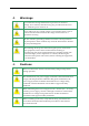
.1 Warnings To avoid electric arcing and hazards to personnel or electrical damage, never connect/disconnect any plug or cable from the servo drive while the power source is on. Power cables can carry a high voltage, even when the motor is not in motion. Disconnect the Trio from all voltage sources before it is opened for servicing. The Trio contains grounding conduits for electric current protection. Any disruption to these conduits may cause the instrument to become hot (live) and dangerous.
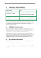
.3 Directives and Standards The Trio conforms to the following industry safety standards: Safety Standard Item In compliance with UL508c Power Conversion Equipment In compliance with UL840 Insulation Coordination, Including Clearance and Creepage Distances of Electrical Equipment In compliance with UL60950-1 (formerly UL1950) Safety of Information Technology Equipment, Including Electrical Business Equipment In compliance with EN60204-1 Low Voltage Directive, 73/23/EEC The Trio has been develope
Introduction This installation guide describes the Trio and the steps for its wiring, installation and powerup. Following these guidelines ensures maximum functionality of the product and the system to which it is connected. .1 Product Description The Trio was designed to be a very compact product oriented for X, Y, Z applications integrating three servo drives in one package and working under one power supply equipped by a built-in shunt regulator.
Sinusoidal commutation with vector control or trapezoidal commutation with encoder and/or digital hall sensors 12-bit current loop resolution Automatic gain scheduling, to compensate for variations in the DC bus power supply .2.2 Velocity Control Fully digital Programmable PI and FFW (feed forward) control filters Sample rate two times current loop sample time “On-the-fly” gain scheduling Automatic, manual and advanced manual tuning and determination of optimal gain and phase margins .2.
• Resolver o Programmable 10~15 bit resolution o Up to 512 Revolution Per Second (RPS) o Auxiliary emulated, unbuffered, single-ended, encoder output • Tachometer, Potentiometer • Elmo drives provide supply voltage for all the feedback options .2.
Figure 2-1: Elmo Digital Servo Drive Documentation Hierarchy As depicted in the previous figure, this installation guide is an integral part of the Trio documentation set, comprising: The Trio User Guide contains information about how to use the Trio and Cable Kit. The Composer Software Manual, which includes explanations of all the software tools that are part of Elmo’s Composer software environment.
Installation .4 Site Requirements You can guarantee the safe operation of the Trio by ensuring that it is installed in an appropriate environment. Feature Value Ambient operating temperature 0 °C to 40 °C (32 °F to 104 °F) Maximum operating altitude 2,000 m (6562 feet) Maximum relative humidity 90% non-condensing Operating area atmosphere No flammable gases or vapors permitted in area Models for extended environmental conditions are available.
The part number at the top of the sticker gives the type designation as follows: Verify that the Trio type is the one that you ordered, and ensure that the voltage meets your specific requirements.
.6 Mounting the Trio The Trio has been designed for two standard mounting options: “Wall Mount” along the back (can also be mounted horizontally on a metal surface) “Book Shelf” along the side M4 round head screws, one through each opening in the heat sink, are used to mount the Trio (see the diagram below).
.7 Connecting the Cables .7.1 Wiring the Trio Once the Trio is mounted, you are ready to wire the device. Proper wiring, grounding and shielding are essential for ensuring safe, immune and optimal servo performance of the Trio. Follow these instructions to ensure safe and proper wiring Use twisted pair shielded cables for control, feedback and communication connections. For best results, the cable should have an aluminum foil shield covered by copper braid, and should contain a drain wire.
Type Function Main Feedback Feedback I/O I/O P&D P&D Connector Location P&D I/O Feedback Table 3-2: Connectors on the “Front” of the Trio Type Function CANopen IN CANopen IN CANopen OUT CANopen OUT RS-232 RS-232-1 RS-232-2 Connector Location 5.
.8 Trio Connector Types Type Main Power Motor Power Main Feedback On Board Connector / Mating Connector Phoenix 1x7-pin Header MSTBA 2.5/7-G-5.08/ Phoenix 1x7-pin Plug MSTBT 2.5/7-ST-5.
.9 Hardware Requirements The components that you will need to install your Trio are: Component Main Power Connector on Board Function 5.08 mm pitch 1x7-pin Header PE, AC2, AC1, VP+, PR, PR, VL 5.08 mm pitch 3x4-pin Header PE, M3, M2, M1 Main Feedback 3x12-pin Molex Header Feedback I/O 3x14-pin Molex Header I/O P&D 3x8-pin Molex Header P&D RS-232 3x8-pin RJ-45 Socket Motor Power CANopen Communication 2x8-pin RJ-45 Socket Cable Drawing Described in section PE VL PE M1 B.3 B.5 B.
.10 Trio Block Diagram Figure 3-1: Trio Block Diagram
.11 The Main Power and Motor Power Connectors Pin Function Cable PE Protective earth Power AC2 Main Voltage Phase 2 Power AC1 Main Voltage Phase 1 Power VP+ Pos. Power input Power PR Power return Power PR Aux. Supply Input Return Aux VL Aux.
Figure 3-2: AC Motor Power Connection Diagram for each AXIS. .11.2 Connecting Main Power There are two possibilities for connection: 1. AC SOURCE RECOMMENDED Connect the AC power supply cable to the AC1, AC2 and PE terminals of the main power connector. Notes for connecting the AC power cable: The source of the 0 ~ 62 VAC Power Supply must be isolated. For the greatest immunity, a shielded (not twisted) cable is recommended (not mandatory) for the AC power supply cable.
2. DC SOURCE OPTIONAL Connect the DC power supply cable to the VP+ and PR terminals of the main power connector. Notes for connecting the DC power supply: The source of the 0 ~ 88 VDC Power Supply must be isolated. For the greatest immunity, it is highly recommended to use twisted and shielded cables for the DC power supply cable. A 3-wire shielded cable should be used. The gauge is determined by the actual current consumption of the motor.
Figure 3-5: Auxiliary Supply Connection Diagram The back-up functionality can be use for storing control parameters in case of power-loss, providing maximum flexibility and backup functionality when needed.
.12 Main Feedback The Main Feedback port is used to transfer feedback data from the motor to the drive. The Trio accepts the following as a main feedback mechanism: Incremental encoder only Incremental encoder with digital hall sensors Digital hall sensors only Incremental analog (sine/cosine) encoder (option) Resolver (option) Tachometer and potentiometer (option) The Main Feedback port on the Trio has a 12-pin Molex Header plug.
Table 3-7: Main Feedback Cable Pin Assignment for Each Axis Figure 3-7: Main Feedback- Incremental Encoder with Digital Halls Sensors Connection Diagram
Figure 3-8: Main Feedback- Incremental Encoder Only Connection Diagram Figure 3-9: Main Feedback – Interpolated Analog Encoder Connection Diagram
Figure 3-10: Main Feedback– Resolver Connection Diagram
Figure 3-11: Main Feedback – Tachometer Feedback with Digital Hall Sensor Connection Diagram for Brushless Motors Figure 3-12: Main Feedback – Tachometer Feedback Connection Diagram for Brush Motors
Figure 3-13: Main Feedback – Potentiometer Feedback with Digital Hall Sensor Connection Diagram for Brushless Motors Figure 3-14: Main Feedback – Potentiometer Feedback Connection Diagram for Brush Motors and Voice Coils
.13 Pulse and Direction (YA[4]=0) The P/D port has an 8-pin Molex Header plug with the following pin-outs.
Figure 3-16: Isolated single ended Pulse-and-Direction – Connection Diagram
Figure 3-17: Non Isolated Pulse-and-Direction – Connection Diagram .14 I/O Each Whistle on the Trio has 6 digital inputs, 2 digital outputs and a single analog input.
The I/O port has a 14-pin Molex Header plug with the following pin-outs.
• When the controller's signal level is ~5 V. The Default Digital Input level Signal is 5 V.
.14.2 Digital Output Figure 3-19: Digital Output Connection Diagram .14.
.15 Communications The communication cables use an 8-pin RJ-45 plug that connect to the RS-232 and CANopen ports on the Trio. The communication interface may differ according to the user’s hardware. The Trio can communicate using the following options: 1. RS-232, full duplex 2. CANopen RS-232 communication requires a standard, commercial 3-core null-modem cable connected from the Trio to a serial interface on the PC. The interface is selected and set up in the Composer software.
Figure 3-21: RS-232 Connection Diagram .15.2 CANopen Communication Notes for connecting the CANopen communication cable: For "daisy-chain" connections, use 26 or 28 AWG twisted pair shielded cables. For best results, the shield should have aluminum foil and be covered by copper braid with a drain wire Connect the shield to the ground of the host (PC). Usually, this connection is soldered internally inside the connector at the PC end. You can use the drain wire to facilitate connection.
Caution: 1. When installing CANopen communications, ensure that each servo drive is allocated a unique ID.
.16 Powering Up After the cables have been connected to their devices, the Trio is ready to be powered up. Caution: 1. Before applying power, ensure that the AC/DC supply are both isolated and within the specified range. 2. When using a DC supply, ensure that the proper plus-minus connections are in order. .17 Initializing the System After the Trio has been connected and mounted, the system must be set up and initialized.
Technical Specifications .
• Event capturing inputs • Event triggered programming structure • Analog inputs o 1 differential inputs with 12-bit resolution • Enable input, limit switches and emergency stop handling • Smart multi-purpose inputs o • Uncommitted programmable inputs o • 2 separated outputs Storage memory o • 6 inputs sharing one single common Uncommitted, programmable outputs o • Programmable as Enable, Forward and Reverse Limit Switches, Home, Capture Large, non-volatile storage of controller paramet
.19 Built-In Protection • Software error handling o • Status reporting o • Software-based Available for a large number of fault conditions Protection against: o Short circuit between motor power outputs o Short circuit between each motor power output and DC bus return o Failure of internal power supply o Heatsink over-temperature o Under/over voltage o Loss of commutation signals o Loss of velocity feedback o “Bad” commutation o Communication error
.20 Trio Dimensions
.21 Power Ratings Feature Unit 1/60 Minimum supply voltage VAC 5.5 8.5 Nominal supply voltage VAC 34 60 Maximum supply voltage VDC 48 88 Max. output power from the drive without heatsink W 50 2.5/60 120 5/60 240 10/60 480 1/100 75 2.
.22 .22.
.22.
Control inputs .23 PLC or +5V level Feedbacks .23.
.23.3 Digital Halls Feature Details Halls inputs H A , H B, H C . Single ended inputs Built in hysteresis for noise immunity. Input voltage Nominal operating range: 0 V < VIn_Hall < 5 V Maximum absolute: -1 V < VIn_Hall < 15 V High level input voltage: V InHigh > 2.5 V Low level input voltage: V InLow < 1 V Input current Sink current (when input pulled to the common): 3 mA Source current: 1.5 mA (designed to also support open collector Halls) Maximum frequency .23.
.23.5 Resolver Feature Details Resolver format Sine/Cosine Differential Input resistance Differential 2.49 kΩ Resolution Programmable: 10 ~ 15 bits Maximum electrical frequency (RPS) 512 revolutions/sec Resolver transfer ratio 0.5 Reference frequency 1/Ts (Ts = sample time in seconds) Reference voltage Supplied by the Whistle Reference current Up to ±50 mA .23.
.23.7 Potentiometer Feature Details Potentiometer Format Single-ended Operating Voltage Range 0 ~ 5 V supplied by the Whistle Potentiometer Resistance 100 Ω ~ 1 kΩ … above this range, linearity is affected detrimentally Input Resistance 100 kΩ Resolution 14 bit .24 .24.1 I/Os Digital Input Interface Feature Type of input Details Optically isolated All six inputs share one signal return line Input current for all inputs Iin = 2.4 mA @ Vin = 5 V High-level input voltage 2.
.24.2 Digital Output Interface Feature Details Type of output Optically isolated Open collector and open emitter Maximum supply output (Vcc) 30 V Max. output current Iout (max) (Vout = Low) Iout (max) ≤ 10 mA VOL at maximum output voltage (low level) Vout (on) ≤ 0.3 V RL External resistor RL must be selected to limit output current to no more than 10 mA.
.25 Mechanical Specifications Feature Details Mounting The Trio will be designed for two standard mounting options: “Wall Mount” along the back (can also be mounted horizontally on a metal surface) “Book Shelf” along the side Overall dimensions 220 x 140 x 30 mm Weight ~ 815 g .
IPC-SM-782 IPC-CM-770 (clearance, creepage, spacing, conductor sizing and so on) UL508c UL840 In compliance with VDE0160 -7 .27.
Cables (Optional) .28 Cable Photos Main Feedback: CBL- HDRFB-001 Pulse and Direction: CBL- HDRPD-001 I/O: CBL- HDRIO-001 RS-232 Com.: CBL-RJ452321 CAN Com.
.29 Cable Kits The cables are all 2 m in length. Each set contains the cables listed below. Additional cable kits and individual cables (individually or in multiples of 10 each) are available from Elmo. Cable Application .30 Cable Part. No.
Figure A-6: Single-sided Main Feedback Cable (Part No. CBL-HDRFB-001) .31 Pulse and Direction (CBL-HDRPD-001) The Pulse and Direction cable (CBL-HDRPD-001) is made of a 24-AWG shielded cable with an 8-pin Molex Header socket. It connects to the Pulse and Direction port on the Trio. Pin No.
Figure A-2: Single-sided Pulse and Direction Cable (Part No. CBL-HDRPD-001) .32 I/O (CBL-HDRIO-001) The I/O cable (CBL-HDRIO-001) is made of a 24-AWG shielded cable with a 14-pin Molex Header socket. It connects to the I/O port on the Trio. Pin No.
12 Red 13 White-Black 14 White-Red pair Figure A-7: Single-sided I/O Cable (Part No. CBL-HDRIO-001) .33 Communication Cables The communication cables use 26-AWG twisted pair shielded cable. They are connected using an 8-pin RJ-45 plug. Elmo drives can communicate using the following options: RS-232 full duplex CANopen .33.1 RJ45 Pin No. RS-232 Option (CBL-RJ452321) Color D-type Female Pin No.
Figure A-4: RS-232 Communications Cable (Part No.
.33.2 RJ45 Pin No. CAN Option (CBL-RJ45CAN1) Color D-type Female Pin No. Signal Description 1 Green 7 CAN-H CAN_H bus line 2 Yellow 2 CAN_L CAN_L bus line 3 White 3 CAN_GND CAN ground 4 — — — — 5 — — — — 7 — — — — 8 — — — — body Drain Wire body shield cable shield 1 The shields of the RJ-45 and D-type plugs are connected to each other through the cable braid. Figure A-5: CAN Cable (Part No. CBL-RJ45CAN1) .
The drain wire is a non-insulated wire that is in contact with parts of the cable, usually the shield. It is used to terminate the shield and as a grounding connection. The impedance of the wire must be as low as possible. The size of the wire must be thicker than actually required by the carrying current. A 24, 26 or 28 AWG wire for control and feedback cables is satisfactory although 24 AWG is recommended. Use shielded wires for motor connections as well.