
Software Manual Owner manual

SimplIQ Software Manual The Current Controller
MAN-SIMSW (Ver. 1.4)
9-2
Pre-filter
Torque
command
Q
P+I controller
Output
Coordinate
transform
D
P+I controller
Power bridge
& motor
Input
Coordinate
transform
Va
Vb
Vc
Ia
Ib
Ic
PWM output
Current sensors
-
Σ
IQ
ID
Σ
-
0
Commutation
angle
θ
VQ
VD
Peak/Continuous limit
saturation
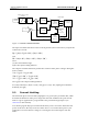
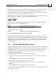
Figure 9-1: Current Controller Structure
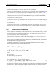
The input coordinate transform retrieves the IQ and ID (active and reactive) components
of the motor current.
)240(hI)120(hI)(hIIQ
cba
oo
+θ++θ+θ=
and
)330(hI)210(hI)90(hIID
cba
ooo
+θ++θ++θ=
where:
θ is the commutation angle.
)(h θ is the input winding function.
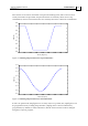
The output coordinate transform predicts the variation of the phase voltages during the
motor rotation:
)90(gV)(gVVA
DQ
o
+θ+θ=
)210(gV)120(gVVB
DQ
oo
+θ++θ=
)330(gV)240(gVVC
DQ
oo
+θ++θ=
where
)(g θ
is the output winding function.
For sinusoidal motors,
)cos()(h
θ
≡θ
and
)cos()(g
θ
≡
θ
. The SimplIQ drive tabulates
both
)(h θ and )(g θ .
9.1 Current Limiting
The maximum phase current of the SimplIQ drive is given by the parameter MC, which
describes the hardware of the power stage and cannot be modified. The peak current
limit for a given application is programmed to the parameter PL[1] amperes (see
section
2.3 in this manual).
You should program PL[1] to be smaller than MC if you do not wish to utilize the full
power of the drive; this may be the case if the drive is oversized with respect to your
application or because the line voltage is not enough to drive MC amperes into the
motor.