
Software Manual Owner manual

SimplIQ Software Manual
MAN-SIMSW (Ver. 1.4)
14-1
Chapter 14: Filters
The filter serves as a basic building block for the SimplIQ drive algorithms. The SimplIQ
drive uses a filter mechanism in the following:
The speed controller high-order filter, which is a control filter placed between the speed
PI controller and the torque controller (see Chapter 15)
The position controller high-order filter, a control filter placed between the position
controller gain and the speed PI controller (see Chapter 15)
The analog reference signal to the speed controller, which can be filtered
Analog position sensors (potentiometer and analog encoder), in which a filter smoothes
the position and speed measurements
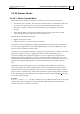
All of these filters are parameterized the same way. Each filter is built by one or more
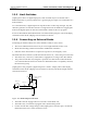
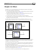
second-order links, connected in a series, as depicted in the following two-block example:
In the top frame, the first block in the series is a second-order low-pass filter; the next one is
a notch filter. The bottom frame contains a fourth-order filter resulting from applying the
notch filter in series with the low-pass filter.
A first-order filter link can be made by setting some of the second-order filter parameters to
zero. The filters are implemented in a normalized form, meaning that the DC gain of each
filter (and of the entire filter series) is 1.0.
Very high-order control filters can be used with the
SimplIQ drive. However, when they are
used, the filter implementation increases the load on the CPU significantly and may require
an increase in the sampling time (TS) (see section
7.3).
The parameters of all filters are programmed into the vector KV[N], as follows:
10
1
10
2
10
3
10
4
10
5
10
-4
10
-3
10
-2
10
-1
10
0
10
1
10
1
10
2
10
3
10
4
10
5
10
-0.8
10
-0.7
10
-0.6
10
-0.5
10
-0.4
10
-0.3
10
-0.2
10
-0.1
1
2
3
4
5
10
-4
10
-3
10
-2
10
-1
10
0
I
n
Out
O
t
In
Two links in series
4th order equivalent