
User guide

Elo TouchSystems 15A2 User Guide 45
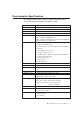
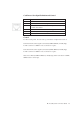
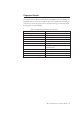
Cash Drawer Port Signal Definition and Control
Pin # Signal Name
1 Frame Ground
2 CD 1 Drawer kick-out drive signal 1
3 SW ( + ) connected on the side of the open/closed detection
switch on the drawer
4 L ( + ) +12V DC for drawer kick-out supplied
5 CD 2 Drawer kick-out drive signal 2
6 ( - ) Ground
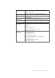
Control
For driver development, the cash drawer port hardware is implemented as below.
Cash drawer kick-out drive signal 1: Generated by ICH6’s GPIO24 (normally high).
To kick-out drawer 1, GPIO24 sends out an active low pulse.
Cash drawer kick-out drive signal 2; Generated by ICH6’s GPIO25 (normally high).
To kick-out drawer 2, GPIO25 sends out an active low pulse.
Status detect: Read by ICH6’S GPIO33 (normally high). When cash drawer is OPEN,
GPIO33 status is active high.