Touchcomputer User Guide 17A2 17" LCD Multifunction Touchcomputer
Elo TouchSystems Touchcomputer User Guide 17" LCD Multifunction Touchcomputer ESY17A2 Revision D P/N E926979 Elo TouchSystems 1-800-557-1458 www.elotouch.
Copyright c 2008 Tyco Electronics. All Rights Reserved. No part of this publication may be reproduced, transmitted, transcribed, stored in a retrieval system, or translated into any language or computer language, in any form or by any means, including, but not limited to, electronic, magnetic, optical, chemical, manual, or otherwise without prior written permission of Elo TouchSystems. Disclaimer The information in this document is subject to change without notice.
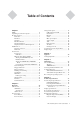
Table of Contents Chapter 1 Setup 6 Unpacking Your Touchcomputer ......................... 6 Product Overview ................................................ 7 Front View ..................................................... 7 Rear View ....................................................... 7 Side View ....................................................... 8 Base Bottom View ......................................... 8 Display Orientation .......................................
Fingerprint Reader ................................... 51 Barcode Scanner ...................................... 52 Speaker Bar .............................................. 53 DVD Drive ................................................ 54 Wireless Card ........................................... 55 TV Tuner .................................................. 55 Environmental Specifications .......................... 56 Temperature Ranges ................................ 56 Humidity .........................
C H A P T E R 1 Setup This chapter discusses how to set up and test your touchcomputer and any included peripheral options.
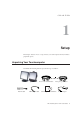
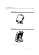
Product Overview Front View Rear View Note: Shown with optional peripherals Elo TouchSystems 17A2 User Guide 7
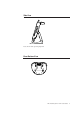
Side View Note: Shown with optional peripherals Base Bottom View Elo TouchSystems 17A2 User Guide 8
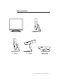
Display Orientation Elo TouchSystems 17A2 User Guide 9
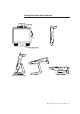
Display Orientation with Peripherals Elo TouchSystems 17A2 User Guide 10
Initial Turn-On The initial setup of the operating system takes approximately 5-10 minutes. Additional time may be needed depending on touchcomputer hardware configuration and connected devices. To setup the Windows OS for the touchcomputer, turn on the touchcomputer and follow the instructions on the screen. Language Selection When the following window appears, you have the option of changing the language used in menus and dialogs. Click Customize.
Select the Language tab. The window shown below will appear. Select the desired language in the drop-down list labeled Language used in menus and dialogs.
Time-zone selection When the following window appears, you may change the time-zone, date, and/or time of the touchcomputer. After making any changes, click Next to finish. Windows Setup will complete the initialization of the touchcomputer.
Test Devices The touchcomputer can be pre-installed with several different hardware options. To test an optional device that is installed on the touchcomputer, follow the instructions below. NOTE: Testing icons are located on the desktop. Testing of a particular device can only be done after the device is properly installed. Testing the Touchscreen The touchscreen is pre-calibrated for accurate touch response.
Testing the Magnetic Stripe Reader (MSR) (optional) Testing in USB MSR Keyboard (KB) Emulation Mode 1. Double-click the KB MSR Test icon to open the Notepad application 2. Slide the card through the MSR and verify that the data is displayed in the application window. Testing in USB MSR Human Interface Device (HID) Mode 1. Double-click the HID MSR Test icon to start the test application. 2. Click the Read Cards button. 3.
Converting MSR from Keyboard Emulation to HID and vice versa 1. Double-click the MSR Change Mode icon to start the switch application. 2. Click on HID Mode to switch to HID mode OR click on Keyboard Mode to switch to Keyboard mode. The dimmed box will indicate the current setting. 3. Click Quit to close the window.
Testing the Customer Display (optional) 1. Double-click the CustDisplay Test icon. 2. Verify that the device shows "EloTouch Systems Customer Display" on the display.
Testing the Finger Print Reader (optional) 1. Double-click the Fingerprint Reader Test icon to start the test application. 2. Place your finger on the fingerprint reader sensor and verify that the image of your fingerprint is displayed on the application window.
Testing the Barcode Scanner (optional) 1. Determine which port the barcode scanner is using: a. In Windows Control Panel, start the Computer Management application b. In Computer Management, select Device Manager. In the Right pane, look under the Ports section, and note the COM value of the USB -Serial Port object. 2.
1. Change the port value to match the value you retrieved from the Device Manager. 2. Click Connect. You should see the text Connected in the Messages field. 3. In the box labeled Param Number, enter the value 238. 4. In the box labeled “New Value” enter the value 1. 5. Check the box labeled Permanent Param Change. 6. Scan a barcode.
Enabling 2-D Scanning: The scanner default settings do not enable 2-D barcode reading ability. In order to enable this option, follow these steps: • Scan the barcodes below to enable PDF417 and MicroPDF417. These are both types of 2-D barcodes. • Now scan the barcode below to change the scanning pattern. Using this scanning pattern will allow you to read 2-D barcodes (you can still read 1-D barcodes also).
Testing the Speaker Bar (optional) To test the speaker bar, play any audio file on the touchcomputer and verify the sound emitting from the speakers. NOTE: If the speaker bar is connected to the touchcomputer, the internal speakers will be disabled. If there is an audio cable plugged into the audio output port on the I/ O panel, both internal and speaker bar speakers will be disabled.
Testing the Wireless Card (optional) To test the wireless card: 1. From the desktop, click Start->Control Panel->Network Connections 2. Double-click the Wireless Network Connections icon to display available networks and verify that the wireless network is detected. Note: If a wireless network needs to be initialized, please see your system administrator.
Testing the Cash Drawer Port To test the cash drawer port, first ensure that a cash drawer port is attached to the touchcomputer using a cable with the correct wiring definition. For additional information, see Cash Drawer Port Signal Definition and Control section on page 44. 1. Double-click the Cash Drawer Test icon to start the test application. 2. Click the Drawer 1 or Drawer 2 box to open the cash drawer. The status line indicates whether the drawer is open or closed.
C H A P T E R 2 Operation This chapter shows the user how to control the On-Screen Display (OSD) and Power buttons, use the I/O panel, securely mount the touchcomputer and adjust the display head. All adjustments made to the OSD and Power controls are automatically saved. User settings will remain unchanged after powering off/on or in the case of a power failure.
OSD Control OSD Menu To display the OSD Menu, press the Menu button. 1. Press the UP button or DOWN button to toggle and the SELECT button to select among the different OSD sub-menus and functions. 2. When the function you want to change is shown, press the SELECT button. To adjust the value of the function: 1. Pressing the UP button increases the value of the selected OSD control option. 2. Pressing the DOWN button decreases the value of the selected OSD control option.
Factory Reset Changes all OSD settings to factory default. Color Reset Changes all OSD color settings to factory default. Position Reset Changes all OSD position settings to factory default. Sharpness Adjusts the sharpness of the display. Volume Adjusts the audio signal level of the internal speakers, speaker bar and audio output. Information The current OSD version is displayed in the exit tab of the main menu. The current resolution and refresh rates are displayed at the bottom of every OSD menu.
Power Control Power Button The power button function can be set by the operating system under: Control Panel->Display Properties->Screen Saver->Power->Advanced->Power Buttons To override all Operating System settings and shut down the touchcomputer, press and hold the power button for 7 seconds. Note: This function will not work if the power button is locked as described in the section below. Power Lockout You are able to lock and unlock the Power button.
Using the I/O panel The touchcomputer provides the following I/O interfaces for connecting a wide variety of compliant devices. USB and Powered USB There are four USB 2.0 type A ports, including one 12V powered USB 2.0 port. Cash Drawer There is one 12V cash drawer port with a six position register jack connector interface. For additional information, see the Cash Drawer Port Signal Definition and Control section on page 44.
VGA There is one D-SUB VGA output port for connecting a secondary display. PS/2 Universal There is one PS/2 Universal port for connecting a keyboard and mouse simultaneously with the supplied Y-cable. A PS/2 keyboard is functional when connected directly to the PS/2 universal port. A PS/2 mouse should NOT be connected directly to the PS/2 universal port without the Y-cable. TV Tuner (optional) There is one TV Tuner input for use when the TV Tuner option is selected.
Securing the Touchcomputer Base Mounting Option 1 1 Snap off stand cover TOP VIEW 2 Mount as shown Note: Dimensions are in millimeters Elo TouchSystems 17A2 User Guide 31
Mounting Option 2 Mount as shown Note: Dimensions are in millimeters Elo TouchSystems 17A2 User Guide 32
Display Angle For viewing clarity, you can tilt the LCD forward up 67 to 90 degrees. CAUTION In order to protect the LCD, be sure to hold the base when adjusting the LCD, and take care not to touch the screen.
C H A P T E R 3 Upgrades Adding Peripherals When adding a peripheral, complete installation and setup instructions are provided with the user-installable kits. The following components are available in user-installable kits.
C H A P T E R 4 Maintenance Elo TouchSystems 17A2 User Guide 35
Care and Handling of Your Touchcomputer The following tips will help keep your Elo touchcomputer functioning at the optimal level. • To avoid risk of electric shock, do not disassemble the power adapter or display unit cabinet. The unit is not user serviceable. Remember to unplug the display unit from the power outlet before cleaning. • Do not use alcohol (methyl, ethyl or isopropyl) or any strong dissolvent. Do not use thinner or benzene, abrasive cleaners or compressed air.
Servicing the Hard Disk Drive and Compact Flash Card When removing or installing a hard disk drive and/or a compact flash card, first turn the touchcomputer off and remove the power supply connection. To Install the Hard Disk Drive 1. Remove the screws closing the DVD drive flap, then remove the flap on the left side of the touchcomputer which covers the DVD drive. If you have an existing hard drive, please pull on the metal handle. After pulling on this handle, the hard drive will easily slide out. 2.
To Install the Compact Flash Card 1. Remove the screw closing the DVD drive flap, then remove flap on the left side of the touchcomputer which covers the DVD drive. 2. If you have an existing CF card, press the black eject button and then remove the existing CF card. 3. Insert the CF card into the slot. When the card is inserted properly, the black eject button will extend out. 4. Close the flap, replace the screw, and replace the back cover insert.
C H A P T E R 5 Technical Specifications Elo TouchSystems 17A2 User Guide 39
Touchcomputer Specifications Note: Not all operating systems or options are supported in all regions. Please contact your local Elo TouchSystems representative for details. Processor RAM Northbridge Southbridge Video Operating systems Ports Expansion Compact Flash Wireless networking BIOS Real Time clock Storage Power supply Power dissipation Temperature Humidity Intel Celeron M 1.0GHz CPU w/400MHz Front-Side Bus 1GB DDR2 RAM standard. Up to 2GB max.
Weight Backlight lamp life Agency approvals Speakers (internal) User controls Mounting options Other features Peripheral Options and Upgrades Actual: 24 lb (10.9kg) Shipping: 32 lb(14.
COM1, COM2 Connector(RS232 Mode) Pin # 1 2 3 4 5 6 7 8 Signal Name Ground Receive Data (RD) Clear to send (CTS) Signal ground Transmit Data (TD) Request to Send (RTS) +5 vdc +5 vdc return RS422 Mode Pin Definition(for COM2 only) Pin # 1 2 3 4 5 6 7 8 Signal Name Ground TX+ TXSignal ground RX+ RX+5 vdc +5 vdc return RS485 Mode Pin Definition(for COM2 only) Pin # 1 2 3 4 5 6 7 8 Signal Name Ground DATA+ DATASignal ground +5 vdc +5 vdc return Elo TouchSystems 17A2 User Guide 42
RJ45 connector Pin Definition Pin # 1 2 3 4 5 6 7 8 Signal Name Receive Data (RD) Clear to Send (CTS) Signal Ground Transmit Data (TD) Request to send DB9 connector Pin Definition Pin # 1 2 3 4 5 6 7 8 9 Signal Name Receive Data (RD) Transmit Data (TD) Signal Ground Request to send Clear to Send (CTS) Power Input Pin Definition Pin # 1 2 3 4 Signal Name +12V Ground Ground +12V Elo TouchSystems 17A2 User Guide 43
Cash Drawer Port Signal Definition and Control Pin # 1 2 3 4 5 6 Signal Name Frame Ground CD 1 Drawer kick-out drive signal 1 SW ( + ) connected on the side of the open/closed detection switch on the drawer L ( + ) +12V DC for drawer kick-out supplied CD 2 Drawer kick-out drive signal 2 ( - ) Ground Control Below is the source code of the test application showing how the cash drawer port is implemented. The cash drawer is controlled by two GPIOS to open the drawer and one GPIO to read back status.
*/ int main(int argc, char *argv[]) { printf("\nELO SBC6 Cash Drawer Demo.\n"); if( is_open() ) printf("\nCash register is open.\n"); else printf("\nCash register is closed.\n"); printf("\nOpening Cash Drawer 1.\n"); open_drawer(DRAWER1); printf("\nOpening Cash Drawer 2.\n"); open_drawer(DRAWER2); if( is_open() ) printf("\nCash register is open.\n"); else printf("\nCash register is closed.
/* ============================================================================= Function: Parameters: Return: Exit: Description: ============================================================================= */ int open_drawer(int drawer) { int data = 0; /* Chipset register data */ int status = 0; /* Cash drawer status signal */ /* Get current cash drawer status. */ status = is_open(); if( status ) { printf("\nCash Register is already open.\n"); return(1); } /* Toggle cash drawer signals - low pulse.
Display Specifications Model LCD Display Display Size Pixel Pitch Display Mode Native Contrast Ratio Brightness LCD AccuTouch IntelliTouch Acoustic Pulse Recognition Response Time Display Color Viewing Angle Plug & Play Touch Panel (optional) 17A2 17.0” TFT Active Matrix Panel 337.92(H) x 270.336(V) mm 0.264(H) x 0.
Power Supply Specifications The touchcomputer shall be powered by 12VDC from a universal type power supply brick with the following characteristics: Input voltage Input frequency Output voltage Output line and load regulation Output current 100 to 240 V~ 50/60 Hz 12 V +/- 5% 10 Amps minimum Elo TouchSystems 17A2 User Guide 48
Touchscreen Specifications Available with Accutouch five-wire resistive (AT), Acoustic Pulse Recognition (APR), and IntelliTouch surface-wave technology. For detailed specifications, please visit our website at www.elotouch.com. Note: Touch options may vary depending on region.
Peripherals Specifications Magnetic Stripe Reader (MSR) The MSR is a USB 1.1 device which reads all three data stripes on standard credit cards or driver’s licenses conforming to ISO/ANSI standards. The MSR will have foreign language capability. The credit card is read by sliding the credit card through the MSR, stripe side toward the display, forward or backward. The MSR is powered from the USB port; no external power is needed.
Fingerprint Reader The fingerprint reader will be ELO part number E728123 (DigitalPersona U.are.U 4000B). The fingerprint reader is powered by the USB bus. The reader optically scans the fingerprint when the user touches the glowing window. Optical technology gives the highest quality fingerprint scans and reliability. Table of Partial Fingerprint Reader Specifications: Fingerprint Reader DigitalPersona U.are.U 4000B Power Supply 5.0Vdc +/- 0.
Barcode Scanner There are two optional USB barcode scanners (1-D or omni-directional). The barcode scanner is only an option if the speaker bar is present. When a scanner is chosen, a USB-SSI (Simple Serial Interface) converter board is included. Both barcode scanners are powered with the USB interface. 1.
Speaker Bar The speaker bar contains two speakers and an audio amplifier. The speakers in the speaker bar provide improved sound quality and higher volumes over the internal speakers. The circuitry is designed such that when the speaker bar is connected to the touchcomputer, the 2 internal speakers will be disabled.
DVD Drive There are two options for the internal slim DVD drive (a combo drive and a burner drive). The DVD drive will be provided with the proper software for CD/DVD playback and CD/DVD recording. 1. The DVD/CD Combo Drive can read and write CDs. It can only read DVDs. The minimum specifications are as follows for the DVD combo drive: • 12.
Wireless Card The wireless card can be selected to provide wireless capabilities. All touchcomputers are "Wireless Ready" and are pre-wired with wireless antennas inside the chassis Typical specifications are as follows for the wireless card: • MiniPCI interface • Compliant to MiniPCI industry standard sizing • 802.
Environmental Specifications Temperature Ranges Operating Temperature (Independent of altitude) o Non-Operating Temperature (Independent of altitude) Humidity Operating (non-condensing) o Non-Operating (38.7 C maximum wet bulb temperature) Altitude Operating Non-Operating o 0 C to 35 C o o -30 C to 60 C 20% to 80% 5% to 95% 0 to + 12,000 feet [3,658m]. Equivalent to 14.7 to 10.1 psia. 0 to + 40,000 feet [12,192m]. Equivalent to 14.7 to 4.4 psia.
C H A P T E R 6 Technical Support Technical Assistance There are three methods to obtain contact information for technical assistance on the touchcomputer: • The touchcomputer • The web • The phone Using the Touchcomputer You can access the support information by going to the System Properties and clicking on the Support Information button.
Regulatory Information I. Electrical Safety Information: A) Compliance is required with respect to the voltage, frequency, and current requirements indicated on the manufacturer’s label. Connection to a different power source than those specified herein will likely result in improper operation, damage to the equipment or pose a fire hazard if the limitations are not followed. B) There are no operator serviceable parts inside this equipment.
This Information Technology Equipment (ITE) is required to have a CE Mark on the manufacturer’s label which means that the equipment has been tested to the following Directives and Standards: This equipment has been tested to the requirements for the CE Mark as required by EMC Directive 89/336/EEC indicated in European Standard EN 55 022 Class A and the Low Voltage Directive 73/23/EEC as indicated in European Standard EN 60 950.
III.
Warranty Except as otherwise stated herein or in an order acknowledgment delivered to Buyer, Seller warrants to Buyer that the Product shall be free of defects in materials and workmanship. The warranty for the touchcomputer and components of the product is regional; please contact your regional office. For contact information, see page 64 or go to www.elotouch.com. Seller makes no warranty regarding the model life of components.
THESE REMEDIES SHALL BE THE BUYER’S EXCLUSIVE REMEDIES FOR BREACH OF WARRANTY. EXCEPT FOR THE EXPRESS WARRANTY SET FORTH ABOVE, SELLER GRANTS NO OTHER WARRANTIES, EXPRESS OR IMPLIED BY STATUTE OR OTHERWISE, REGARDING THE PRODUCTS, THEIR FITNESS FOR ANY PURPOSE, THEIR QUALITY, THEIR MERCHANTABILITY, THEIR NONINFRINGEMENT, OR OTHERWISE. NO EMPLOYEE OF SELLER OR ANY OTHER PARTY IS AUTHORIZED TO MAKE ANY WARRANTY FOR THE GOODS OTHER THAN THE WARRANTY SET FORTH HEREIN.
Check out Elo’s Website! www.elotouch.com Get the latest... • Product information • Specifications • News on upcoming events • Press release • Software drivers • Touchmonitor Newsletter Getting in Touch with Elo To find out more about Elo’s extensive range of touch solutions, visit our Website at www.elotouch.