Touchmonitor User Guide 1519L 15.6” LCD Desktop Touchmonitor 1919L 18.
Elo Touch Solutions 15.6” and 18.5” LCD Touchmonitor Optional Magnetic Stripe Reader User Guide Revision C P/N E356416 Elo Touch Solutions 1-800-ELOTOUCH www.elotouch.
Copyright © 2012 ELO Touch Solutions. All Rights Reserved. No part of this publication may be reproduced, transmitted, transcribed, stored in a retrieval system, or translated into any language or computer language, in any form or by any means, including, but not limited to, electronic, magnetic, optical, chemical, manual, or otherwise without prior written permission of ELO Touch Solutions. Disclaimer The information in this document is subject to change without notice.
Table of Contents Chapter 1 Introduction Chapter 4 Troubleshooting 5 26 Solutions to Common Problems .................................26 Product Description ....................................................5 Precautions.................................................................5 Appendix A Chapter 2 Installation and Setup Native Resolution .......................................................27 6 Unpacking Your Touchmonitor ....................................
C HAPTE R 1 INTRODUCTION Product Description Your new 1519/1919L touchmonitor combines the reliable performance of touch technology with the latest advances in LCD display design. This combination of features creates a natural flow of information between a user and your touchmonitor. This LCD monitor incorporates a 15.6” or 18.5” color active matrix thin-film-transistor (TFT) liquid crystal display to provide high quality display performance.
C HAPTE R 2 INSTALLATION AND SETUP This chapter discusses how to install the 1519L/1919L LCD touchmonitor and the driver software.
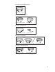
Power cable for North America models USA/UL Power cable Power cable for European models Europe/VDE power cable UK power cable Power cable for Japan models Japanese/PSE power cable Adapter/Terminal Power cable for Asia models and and or or China/CCC power cable Taiwan/BSMI power cable Korea/KC power cable Power cable for Worldwide models USA/UL Power cable Europe/VDE power cable 2-7
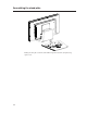
Assembling the stand plate Pushing the stand plate toward the stand untill it is tight, then fasten the stand plate using captive screw.
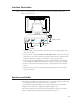
Interface Connection Note: Before connecting the cables to your touchmonitor and PC, be sure that the computer and touchmonitor are turned off. Headphone Cable 1 2 3 2 Serial Cable 4 Audio Cable VGA Cable USB Cable Power Brick 1. Connect DC cable of the power brick to the monitor and the other end through AC power cable to the AC outlet. 2.
Magnetic Stripe Reader (MSR) Interface Connection (optional) If the MSR is installed on the monitor, plug the USB cable from the MSR directly to the PC. No drivers are required to be loaded. To change the MSR function mode from keyboard emulation to HID, load the “MSR CHANGE MODE.EXE” utility from the enclosed TouchTools CD or go online to www.elotouch.com to download this utility. Note: MSR function mode can be changed to HID mode from keyboard emulation mode and back using the “MSR CHANGE MODE.
Product Overview Main Unit Rear View Kensington TM Lock The KensingtonTM lock is a security device that prevents theft. To find out more about this security device, go to http://www.kensington.com.
Mounting the Display Your medically certified touchscreen display conforms to the VESA Flat Panel Monitor Physical Mounting Interface (FPMPMI) standard. The FPMPMI standard defines a physical mounting interface for flat panel displays. Your display conforms to the corresponding standards for flat panel display mounting devices, such as for walls and table arms. The VESA mounting interface is located on the back of your touchscreen display and is pre-connected to the pedestal.
Rear Mounting Using the VESA Interface 1 If the display is already connected to a pedestal, remove the four screws that connect the pedestal to the display (refer to Figure2-1 , item 1 ). Separate the pedestal from the display. 2 Reinstall the four screws into the VESA interface mount. Ensure that the monitor is positioned with the correct side up. 3 Mount the monitor to the wall according to the template shown in Figure 2-2. Route the cables through the cable access opening.
Installing the Driver Software ELO Touch Solutions provides driver software that allows your touchmonitor to work with your computer. Drivers are located on the enclosed CD-ROM for the following operating systems: • Windows 7 • Windows Vista • Windows XP • • • • • Windows 2000 Windows Me Windows 98 Windows 95 Windows NT 4.0 • Windows 3.1 • MS-DOS Additional drivers and driver information for other operating systems are available on the ELO Touch Solutions web site at www.elotouch.com.
Installing the Serial Touch Driver (not applicable to Acoustic Pulse Recognition and Projected-Capacitive monitor) Installing the Serial Touch Driver for Windows 7, Windows Vista, Windows XP, Windows 2000, 98/95, ME and NT4.0 NOTE: For Windows 2000 and NT4.0 you must have administrator access rights to install the driver. Make sure the serial connector (RS232) is plugged into the monitor and an open com port on the PC. 1 Insert the ELO CD-ROM in your computer's CD-ROM drive.
Installing the Serial Touch Driver for Windows 3.1 and MS-DOS You must have a DOS mouse driver (MOUSE.COM) installed for your mouse if you wish to continue using your mouse along with your touchmonitor in DOS. To install Windows 3.x and MS-DOS touch driver from Windows 98/95, follow the directions below: 1 Insert the CD-ROM in your computer’s CD-ROM drive. 2 From DOS, type d: and press the Enter key to select the CD-ROM (your CD-ROM drive may be mapped to a different drive letter).
Installing the USB Touch Driver Installing the USB Touch Driver for Windows 7, Windows Vista, Windows XP, Windows 2000, ME and Windows 98. 1 Insert the ELO CD-ROM in your computer’s CD-ROM drive. If Windows 2000 or Windows 98 starts the Add New Hardware Wizard, do the following: 2 Choose Next. Select “Search for the best driver for your device (Recommended)” and choose Next.
C HAPTE R 3 OPERATION About Touchmonitor Adjustments Your touchmonitor will not likely require adjustment. However, variations in video output and application may require adjustments to the touchmonitor to optimize the quality of the display. For best performance, the input video resolution should be the touchmonitors native resolution, 1366 x 768. Use the Display control panel in Windows to choose 1366 x 768 resolution. Operating in other resolutions will degrade video performance.
Bottom Panel Controls SELECT MENU Audio Output SELECT 5 4 MENU 3 2 1 Control 1 Menu/Exit Function Display/Exits the OSD menus. 2 1. Enter Luminance of the OSD. 2. Increase value of the adjustment item. 3. Move OSD selection upward. 3 1. Enter Audio of the OSD. 2. Decrease value of the adjustment item. 3. Move OSD selection downward . 4 Select 1. Auto adjust function. 2. Select the adjustment item from the OSD menu. 5 Power Switch Switch the power of the monitor.
Controls and Adjustment On Screen Display (OSD) Menu Functions To Display and Select the OSD Functions: 1. Press the Menu key to activate the OSD menu. 2. Use or to move upward or downward through the menu. Press the “Select” key, execute the function or enter the sub-menu. 3. To quit the OSD screen at any time during the operation, press the Menu key. If no keys are pressed for a short time period, the OSD automatically disappears.
On Screen Display(OSD) Control Options Control Auto-Adjust Luminance .Brightness .Contrast Image Setting .H-Position .V-Position .Clock .Phase Color Description Select “Auto-Adjust” to enable this function. The Auto-Adjust will automatically adjust V-Position, H-Position, Clock and Phase. Increases or decreases brightness Increases or decreases contrast Moves the screen left or right Moves the screen up or down The dot clock is fine-adjusted after auto adjust.
Preset Modes To reduce the need for adjustment for different modes, the monitor has default setting modes that are most commonly used as given in the table below. If any of these display modes are detected, the monitor automatically adjusts the picture size and centering. When none of the modes are matched, the user can store their preferred modes in the user modes. The monitor is capable of storing up to 7 user modes.
Power Management System Mode On Sleep Off Power Consumption (12VDC input) <42W <2W <1W It is recommended to switch the monitor off when it is not in use for a long period of time. NOTE: Complies to VESA Power Management (DPM) standards. To activate the monitor, press any key on the keyboard or move the mouse or touch the touchscreen. In order for the touchscreen to bring the monitor from the DPM system, the touchscreen function must be fully operational.
IntelliTouch Plus Touch Technology When connected to Windows 7 computers, the touchmonitor can report 2 simultaneous touches. The IntelliTouch Plus touchscreen can be re-calibrated to your displayed video image, if needed, through the Calibration function in the ELO driver control panel. The IntelliTouch Plus driver will only support multiple monitor if they are all using the IntelliTouch Plus touch technology.
Projected-Capacitive Touch Technology When connected to Windows 7 computers, the touchmonitor can report 2 simultaneous touches. When connected to Windows XP computers, the touchmonitor reports single touches. No additional drivers are required for this technology to work, it uses Windows HID drivers. No calibration is required for this technology. Gesture Support The IntelliTouch Plus and Projected-Capacitive touch technologies enable several gestures that support single and multiple contacts.
C HAPTE R 4 TROUBLESHOOTING If you are experiencing trouble with your touchmonitor, refer to the following table. If the problem persists, please contact your local dealer or the ELO’service center. Solutions to Common Problems Problem The monitor does not respond when turning on the system. Suggestion(s) 1. Check that the monitor’s Power Switch is on. 2. Turn off the power and check the monitor’s DC power cord and signal cable for proper connection.
APPEN D I X A NATIVE RESOLUTION The native resolution of a monitor is the resolution level at which the LCD panel is designed to perform best. For the LCD touchmonitor, the native resolution is 1366 x 768 for the 15.6 inch and 18.5 inch size. In almost all cases, screen images look best when viewed at their native resolution. The resolution setting of a monitor can be lowered but not increased.
As an example, a SVGA resolution LCD panel has 800 pixels horizontally by 600 pixels vertically. Input video is also represented by the same terms. XGA input video has a format of 1024 pixels horizontally by 768 pixels vertically. When the input pixels contained in the video input format match the native resolution of the panel, there is a one to one correspondence of mapping of input video pixels to LCD pixels.
APPEN D I X B TOUCHMONITOR SAFETY This manual contains information that is important for the proper setup and maintenance of your touchmonitor. Before setting up and powering on your new touchmonitor, read through this manual, especially Chapter 2 (Installation), and Chapter 3 (Operation). 1 To reduce the risk of electric shock, follow all safety notices and never open the touchmonitor case. 2 Turn off the product before cleaning.
Care and Handling of Your Touchmonitor The following tips will help keep your touchmonitor functioning at the optimal level. • To avoid risk of electric shock, do not disassemble the brick power supply or display unit cabinet. The unit is not user serviceable. Remember to unplug the display unit from the power outlet before cleaning. • Do not use alcohol (methyl, ethyl or isopropyl) or any strong dissolvent. Do not use thinner or benzene, abrasive cleaners or compressed air.
APPEN D I X C TECHNICAL SPECIFICATIONS C-31
Touchmonitor Specifications Model LCD Display Display Size Pixel Pitch Native Resolution Display Mode Contrast Ratio Brightness Response Time Display Color Viewing Angle Input Video Signal Type Sync Connector Bottom Controls Speakers Audio Input Connector Headphone Output connector OSD Plug & Play Touch Panel Power Adapter Operating Conditions Storage Conditions Dimensions (HxWxD) Weight (Net) Certifications C-32 Temperature Humidity Altitude Temperature Humidity Altitude 1519L 15.
Touchmonitor Specifications Model LCD Display Display Size Pixel Pitch Native Resolution Display Mode Contrast Ratio Brightness Response Time Display Color Viewing Angle Input Video Signal Type Sync Connector Bottom Controls Speakers Audio Input Connector Headphone Output connector OSD Plug & Play Touch Panel Power Adapter Operating Conditions Storage Conditions Dimensions (HxWxD) Weight (Net) Certifications Temperature Humidity Altitude Temperature Humidity Altitude 1919L 18.
15" LCD Touchmonitor (1519L) Dimensions 235 0 383 0 344.2 = = - =;ti1i 62 5 8 l l d.Li l[j - a; - /; -1 - /; 4 3. 6 I 9"'· 6 Mt-11 I 92 6 " 140.0 C-34 V'=lll II 1un · !L IlLII - 'WII I - 1 - ,I 240.
19" LCD Touchmonitor (1919L) Dimensions 179 05 453 92 409.80 = M = ro en I ru ru 50.931_ ??111 It -l = = = = = M M = = = 175.
REGULATORY INFORMATION I. Electrical Safety Information: A) Compliance is required with respect to the voltage, frequency, and current requirements indicated on the manufacturer’s label. Connection to a different power source than those specified herein will likely result in improper operation, damage to the equipment or pose a fire hazard if the limitations are not followed. B) There are no operator serviceable parts inside this equipment.
D) General Information to all Users: This equipment generates, uses and can radiate radio frequency energy. If not installed and used according to this manual the equipment may cause interference with radio and television communications. There is, however, no guarantee that interference will not occur in any particular installation due to site-specific factors.
III.
WARRANTY Except as otherwise stated herein or in an order acknowledgment delivered to Buyer, Seller warrants to Buyer that the Product shall be free of defects in materials and workmanship. The warranty for the touchmonitors and components of the product is 3 (three) years. Seller makes no warranty regarding the model life of components. Seller’s suppliers may at any time and from time to time make changes in the components delivered as Products or components.
THESE REMEDIES SHALL BE THE BUYER’S EXCLUSIVE REMEDIES FOR BREACH OF WARRANTY. EXCEPT FOR THE EXPRESS WARRANTY SET FORTH ABOVE, SELLER GRANTS NO OTHER WARRANTIES, EXPRESS OR IMPLIED BY STATUTE OR OTHERWISE, REGARDING THE PRODUCTS, THEIR FITNESS FOR ANY PURPOSE, THEIR QUALITY, THEIR MERCHANTABILITY, THEIR NONINFRINGEMENT, OR OTHERWISE. NO EMPLOYEE OF SELLER OR ANY OTHER PARTY IS AUTHORIZED TO MAKE ANY WARRANTY FOR THE GOODS OTHER THAN THE WARRANTY SET FORTH HEREIN.
Check out Our Website! www.elotouch.com Get the latest... • Product information • Specifications • News on upcoming events • Press release • Software drivers • Touchmonitor Newsletter Getting in Touch with us To find out more about ELO’s extensive range of touch solutions, visit our website at www.elotouch.