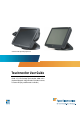
* Shown with optional peripherals Touchmonitor User Guide 1529L 15” LCD Desktop Touchmonitor, 3000 series (Optional Magnetic Stripe Reader, Barcode Scanner, Customer Display and Biometric available)
Elo Touchmonitor User Guide 15" LCD Desktop 1529L Revision E P/N 008603E Elo TouchSystems. 1-800-ELOTOUCH www.elotouch.
Copyright © 2008 Tyco Electronics. All Rights Reserved. No part of this publication may be reproduced, transmitted, transcribed, stored in a retrieval system, or translated into any language or computer language, in any form or by any means, including, but not limited to, electronic, magnetic, optical, chemical, manual, or otherwise without prior written permission of Elo TouchSystems. Disclaimer The information in this document is subject to change without notice.
Table of Contents Chapter 1 Introduction 1 Product Description ................................................. 1 Detailed LCD Display Performance Requirements .......................................................... 2 Customer Display .............................................. 3 Serial Version ................................................. 3 Fingerprint Reader ............................................ 3 Theory of Operation ....................................... 4 Sensor Specifications ....
Appendix B Touchmonitor Safety 45 Care and Handling of Your Touchmonitor ........... 46 Appendix C Technical Specifications Touchmonitor Specifications ......................... AccuTouch Touchscreen Specifications ................................................ IntelliTouch Touchscreen Specifications ................................................ Infrared Touchscreen Specifications ................................................ Acoustic Pulse Recognition Specifications ...........................
C H A P T E R 1 INTRODUCTION Product Description The 1529L is a retail terminal designed to present information to the operator and the customer. The 1529L is available in serial and USB versions or combo touch monitor. The 1529L consists of a 15.0” LCD main display with a touchscreen and the following optional peripherals: customer display, vacuum fluorescent display (VFD) Customer Display, fingerprint reader, barcode scanner, credit card reader, and a 6 port USB (USB version only) Hub.
The credit card reader reads all three stripes on a standard credit card or drivers license. The credit card is read by sliding the credit card, stripe side toward the display through the credit card reader forward or backward. There is a USB credit card reader only. The Hub provides 4 internal USB ports to be used by the credit card reader, the fingerprint reader or barcode scanner, the touchscreen, and the customer display.
Customer Display The Customer Display is a twenty character two line vacuum fluorescent display (VFD). It consists of a VFD and VFD controller. Serial Version Optional Parameters Characters per row Number of rows Character configuration Character Height Character width Character configuration Character color MTBF 20 2 5x7 dot matrix 9.5mm 6.2mm ASCII Blue green 300,000 hours Fingerprint Reader There is a fingerprint reader in the USB version only.
Specifications Sensor Image Capture Speed Image Transfer Speed Pixel Resolution USB Signaling Type SecuGen FOR 600ms/frame 500Byte/ms 356x292 Full Speed Type Theory of Operation The USB host initiates communication with the FDU01 using operation commands (Sensor LED On, Fingerprint Capture Start and Stop). Fingerprint data are then captured by the CMOS sensor at a total image size of 356 x 292 with 8-bit gray level. The image frame transfer speed is 500 bytes/ms.
5. Effective form factor; ability to be mounted on side of ET1529L 6. USB interface that complies with USB 2.0 standards 7. USB bus powered 8. Easy communication between host and scanner 9. Visible laser diode operating at 650nm 10.600+ scans/sec 1-D scanner: 1. Ability to read 1-D codes 2. Scan angle Minimum: 47º ± 3º 3. Low cost solution 4. Effective form factor; ability to be mounted on side of ET1529L 5. USB interface that complies with USB 2.0 standards 6. USB bus powered 7.
1-6 Elo Touchmonitor User Guide
C H A P T E R 2 INSTALLATION AND SETUP This chapter discusses how to install your LCD touchmonitor and how to install Elo TouchSystems driver software.
Product Overview Main Unit Note: Shown with optional Biometric & MSR. Rear View Note: Shown with optional Rear Facing Customer Display.
Side View Base Bottom View or 2-9
Kensington TM Lock The KensingtonTM lock is a security device that prevents theft. To find out more about this security device, do to http://www. kensington.com.
USB Interface Connection Your touchmonitor comes with only one touchscreen connector cables: USB cable. (For Windows 2000, Me and XP systems only.) To set up the display, please refer to the following figures and procedures: Remove the Cable Cover The cables are connected at the back of the monitor. cable cover To remove the cover, grasp the lip of the cover and pull towards you until it snaps off.
CAUTION Before connecting the cables to your touchmonitor and PC, be sure that the computer and touchmonitor are turned off. NOTE Before connecting the cables to the touchmonitor, route all the cables through the hole in the second as shown in the picture above.
The following illustrations guide you step by step in connecting your touchmonitor using a USB cable connection. Power cord Connect one end of the power cord to the monitor and the other end to wall. Connect the power cable to the power port in the monitor.
Video cable Connect one end of the video cable to the rear side of computer and the other to the LCD. Tighten by turning the two thumb screws clockwise to ensure proper grounding. You can select DVI video cable or D-SUB15 video cable.
Speaker cable Connect one end of the speaker cable to the speaker port in the computer and the other end to the port in the monitor.
USB cable Connect one end of the USB cable to the rear side of the computer and the other to the LCD monitor. The USB cable is for optional touch, MSR, CD and Finger Print Reader. Only one USB cable is needed because the device contains a self powered USB 1.1 Hub. Two self powered ports are available for running other USB devices. For touch only, no USB Hub is present.
USB / SERIAL Interface Connection Your touchmonitor comes with only one touchscreen connector cables: USB cable. (For Windows 2000, Me and XP systems only.) To set up the display, please refer to the following figures and procedures: Remove the Cable Cover The cables are connected at the back of the monitor. cable cover To remove the cover, grasp the lip of the cover and pull towards you until it snaps off.
CAUTION Before connecting the cables to your touchmonitor and PC, be sure that the computer and touchmonitor are turned off. NOTE Before connecting the cables to the touchmonitor, route all the cables through the hole in the second as shown in the picture above.
The following illustrations guide you step by step in connecting your touchmonitor using a USB cable connection. Power cord Connect one end of the power cord to the monitor and the other end to wall. Connect the power cable to the power port in the monitor.
Video cable Connect one end of the video cable to the rear side of computer and the other to the LCD. Tighten by turning the two thumb screws clockwise to ensure proper grounding. You can select DVI video cable or D-SUB15 video cable.
Speaker cable Connect one end of the speaker cable to the speaker port in the computer and the other end to the port in the monitor.
USB cable Serial cable For USB interface, connect one end of the USB cable to the rear side of the computer and the other to the LCD monitor. For Serial interface, connect one end of the RS-232 cable to the rear side of the conputer and the other to the LCD monitor.
Replace the Cable Cover Cable cover lip cables Then you have attached all the cables to the monitor, gently bring all the cables toward the standard so they fit under the cover lip. Snap the Cable cover in place over the connections.
Optimizing the LCD Display To ensure the LCD display works well with your computer, configure the display mode of your graphic card to make it less than or equal to 1024 x 768 resolution, and make sure the timing of the display mode is compatible with the LCD display. Refer to Appendix A for more information about resolution. Compatible video modes for your touchmonitor are listed in Appendix C.
Magnetic Stripe Reader No device are needed. Testing the USB MSR Keyboard Emulation 1 Plug in the device. 2 Open MS Word. 3 Slide the card through the MSR to view the data. Testing the USB-HID Class MSR 1 On the CD, browse to Touch Monitor Peripherals\Magnetic Stripe Card Readers\Demo. 2 Open the Readme.txt and follow instructions to test the unit. Convert MSR from HID to keyboard Emulation 1 To convert from HID mode to Keyboard Emulation mode 1.
Convert MSR from keyboard emulation to HID 1 To convert from Keyboard Emulation mode to HID mode 1.1 Double-click on the “MSR Change Mode” icon on the desktop. The following will appear: 1.2 The dim box will indicate the current setting. Click the “HID Mode” to switch to HID mode. 1.3 Click “Quit” to close the window. Rear Facing Customer Display 1. Insert your Elo TouchTools CD. 2. On the CD, browse to Touch Monitor Peripherals\Rear Facing Customer Display\Drivers\USB Drivers.
Barcode Scanner 1. 2. 3. 4. Insert your Elo TouchTools CD. On the CD, browse to Touch Monitor Peripherals\Barcode Scanner Startup\Drivers. Double-click on USB7210.msi and follow the prompts given by the setup file. Once you have finished installing the above: Right click on My Computer and click on Properties. Click on the Hardware tab and then click Device Manager. 5. Double click on USB7210 Converter Module, which should be located in the Other Devices section. Next click on Reinstall Driver. 6.
2) Now scan the barcode below to change your scanning pattern. Using this scanning pattern will allow you to read 2-D barcodes (you can still read 1-D barcodes also). The scanner module also adds a Hall Effect Switch (HE Switch) that enables the unit to automatically set the Trigger mode of the Scan Engine depending on the location of an external magnet (included in scanner cradle).
Installing the Touch Driver Software Elo TouchSystems provides driver software that allows your touchmonitor to work with your computer. Drivers are located on the enclosed CD-ROM for the following operating systems: • Windows XP • Windows 2000 • Windows Me • Windows 98 • Windows 95 • Windows NT 4.0 • CE 2.x, 3.0, 4x • Windows XP Embedded • Windows 3.
Installing the USB Touch Driver Installing the USB Touch Driver for Windows XP, Windows 2000, Me and 98 1 Insert the Elo CD-ROM in your computer’s CD-ROM drive. If Windows XP, Windows 2000,Windows 98, or Windows Me starts the Add New Hardware Wizard: 2 Choose Next. Select “Search for the best driver for your device (Recommended)” and choose Next. 3 When a list of search locations is displayed, place a checkmark on “Specify a location” and use Browse to select the \EloUSB directory on the Elo CD-ROM.
C H A P T E R 3 OPERATION About Touchmonitor Adjustments Your touchmonitor will unlikely require adjustment. Variations in video output and application may require adjustments to your touchmonitor to optimize the quality of the display. For best performance, your touchmonitor should be operating in native resolution, that is 1024 x 768 at 60-75 Hz. Use the Display control panel in Windows to choose 1024 x 768 resolution. Operating in other resolutions will degrade video performance.
15” LCD Function Key 5 4 3 2 1 1 Controls Power Switch Function Turns the display system power on or off. 2 Select Displays the OSD menus on the screen and used to select (“Clockwise” and “Counter-clockwise” direction) the OSD control options 3 on the screen. Adjusts the decreasing value of the selected 4 OSD control option. Adjusts the increasing value of the selected OSD control option. 5 Menu Menu display and menu exit.
Controls and Adjustment OSD Lock/Unlock You are able to lock and unlock the OSD feature. The monitor is shipped in the unlocked position. To lock the OSD: 1 Press the Menu button and button simultaneously for 2 seconds. A window will appear displaying “OSD Unlock”. Continue to hold the buttons down for another 2 seconds and the window toggles to “OSD Lock”. Power Lock/Unlock You are able to lock/unlock the Power feature. The monitor is shipped in the unlockedposition.
OSD Control Options Brightness • Background Luminance of the LCD panel is adjusted. Contrast • Adjusts the contrast or the values of color gain (RED, GREEN or BLUE). Sharpness • The sharpness can be adjustable. Phase • Adjusts the phase of the dot clock. Auto Adjust • Clock system auto adjustment (under 5 seconds). OSD Left/Right • The OSD screen is moved vertically right and left. OSD Up/Down • The OSD screen is moved vertically up and down.
Power-Save (No Input) • The LCD panel background is cut when there is no signal input (AC line power consumption of 4w or less). Power LED Display & Power Saving General Power Saving Mode When the power switch are switch on, this LED lights in green. The LED indicates the different power status with altered LED colors when monitor operates in different modes (see following table). Mode On Sleep Off Power Consumption 50w max. 4w max.
CAUTION In order to protect the LCD, be sure to hold the base when adjusting the LCD, and take care not to touch the screen.
Controls and Adjustment OSD Lock/Unlock You are able to lock and unlock the OSD feature. The monitor is shipped in the unlocked position. To lock the OSD: 1 Press the Menu button and button simultaneously for 2 seconds. A window will appear displaying “OSD Unlock”. Continue to hold the buttons down for another 2 seconds and the window toggles to “OSD Lock”. Power Lock/Unlock You are able to lock/unlock the Power feature. The monitor is shipped in the unlockedposition.
OSD Control Options Brightness • Background Luminance of the LCD panel is adjusted Contrast • Gain of R, G, and B signal is adjusted. Sharpness • The sharpness can be adjustable. Phase • The phase of the dot clock is adjusted. Auto Adjust • Automatically adjusts the systems dot clock(takes approximately 5 seconds). OSD Left/Right • The osd screen is moved horizontally left and right. OSD Up/Down • The OSD screen is moved vertically up and down.
Recall Defaults • Restore all original factory defaults. OSD Timeout • Adjust how long the OSD menu is displayed. Input Video Select • Select D-SUB Analog, dvi Digital signal. Volume • To increase or decrease the sound level.
3-40 Elo Touchmonitor User Guide
C H A P T E R 4 TROUBLESHOOTING If you are experiencing trouble with your touchmonitor, refer to the following table. If the problem persists, please contact your local dealer or our service center. Elo Technical Support numbers are listed on the last page of this manual. Solutions to Common Problems Problem Suggestion(s) The monitor does not respond after Check that the monitor’s Power Switch is on. you turn on the system.
4-42 Elo Touchmonitor User Guide
C H A P T E R A NATIVE RESOLUTION The native resolution of a monitor is the resolution level at which the LCD panel is designed to perform best. For the Elo LCD touchmonitor, the native resolution is 1024 x 768 for the 15.0 inch size. In almost all cases, screen images look best when viewed at their native resolution. You can lower the resolution setting of a monitor but not increase it. Input Video 15.
As an example, a SVGA resolution LCD panel has 800 pixels horizontally by 600 pixels vertically. Input video is also represented by the same terms. XGA input video has a format of 1024 pixels horizontally by 768 pixels vertically. When the input pixels contained in the video input format match the native resolution of the panel, there is a one to one correspondence of mapping of input video pixels to LCD pixels.
C H A P T E R B TOUCHMONITOR SAFETY This manual contains information that is important for the proper setup and maintenance of your touchmonitor. Before setting up and powering on your new touchmonitor, read through this manual, especially Chapter 2 (Installation), and Chapter 3 (Operation). 1 To reduce the risk of electric shock, follow all safety notices and never open the touchmonitor case. 2 Turn off the product before cleaning 3 Your new touchmonitor is equipped with a 3-wire, grounding power cord.
Care and Handling of Your Touchmonitor The following tips will help keep your Elo Entuitive touchmonitor functioning at the optimal level. • To avoid risk of electric shock, do not disassemble the brick supply or display unit cabinet. The unit is not user serviceable. Remember to unplug the display unit from the power outlet before cleaning. • Do not use alcohol (methyl, ethyl or isopropyl) or any strong dissolvent. Do not use thinner or benzene, abrasive cleaners or compressed air.
C H A P T E R C TECHNICAL SPECIFICATIONS Display Modes Your Elo Entuitive touchmonitor is compatible with the following standard video modes: Item Resolution Type H. Scan(KHz) V. Scan(Hz) Pol. 1 2 640X350 720X400 VGA VGA 31.469 31.469 70.087 70.087 +/ -/+ 3 4 640X480 640X480 VGA VESA72 31.469 37.861 59.940 72.809 -/ -/ 5 6 640X480 800X600 VESA75 SVGA 37.500 35.156 75.000 56.250 -/ +/+ 7 8 800X600 800X600 SVGA VESA72 37.879 48.077 60.317 72.
Touchmonitor Specifications Model LCD Display 1529L 15.0” TFT Active Matrix Panel Display Size Pixel Pitch 304.1(H) x 228(V) mm 0.297(H) x 0.
AccuTouch Touchscreen Specifications Mechanical Construction Top: Polyester with outside hard-surface coating with clear or antiglare finish. Inside: Transparent conductive coating. Bottom: Glass substrate with uniform resistive coating. Top and bottom layers separated by Elo-patented separator dots. Positional Accuracy Standard deviation of error is less than 0.080 in. (2.03 mm). This equates to less than ±1%.
IntelliTouch Touchscreen Specifications Mechanical Positional Accuracy Standard deviation of error is less than 0.080 in. (2.03 mm). Equates to less than ±1%. Touchpoint Density Touch Activation Force More than 100,000 touchpoints/in2 (15,500 touchpoints/cm2). Typically less than 3 ounces (85 grams). Surface Durability Expected Life Performance Surface durability is that of glass, Mohs’ hardness rating of 7. No known wear-out mechanism, as there are no layers, coatings, or moving parts.
Infrared Touchscreen Specifications Mechanical Input Method Electrical Input Method Finger or gloved hand activation Positional Accuracy Resolution Typical centroid accuracy: 2 mm with 1 mm STD error Touchpoint density is based on controller resolution of 4096 x Touch Activation Force 4096 No minimum touch activation force is required Controller Optical Board: Serial (RS232) or USB 1.
Acoustic Pulse Recognition Specification MECHANICAL Input method Finger, finger nail, gloved hand, or stylus activation ELECTRICAL Position accuracy 1% max. error Resolution accuracy Touch activation force Touchpoint density is based on controller resolution of 4096 x 4096 Typically 2 to 3 ounces (55 to 85 grams) Controller OPTICAL Board: USB 1.
15” LCD Touchmonitor(ET1529L-XXXA-1-XX-G) Dimensions 15” LCD Touchmonitor(ET1529L-XXXA-1-XX-T-G) Dimensions C-53
C-54 Elo Touchmonitor User Guide
REGULATORY INFORMATION I. Electrical Safety Information: A) Compliance is required with respect to the voltage, frequency, and current requirements indicated on the manufacturer’s label. Connection to a different power source than those specified herein will likely result in improper operation, damage to the equipment or pose a fire hazard if the limitations are not followed. B) There are no operator serviceable parts inside this equipment.
This Information Technology Equipment (ITE) is required to have a CE Mark on the manufacturer’s label which means that the equipment has been tested to the following Directives and Standards: This equipment has been tested to the requirements for the CE Mark as required by EMC Directive 89/336/EEC indicated in European Standard EN 55 022 Class B and the Low Voltage Directive 73/23/EEC as indicated in European Standard EN 60 950.
REP AR U B L I CA G E N TI N A "The application of this monitor is restricted to special controlled luminous environments.The screen surface trend to reflect annoying light of lamps and sunlight. To avoid these reflections the monitor should not be positioned in front of a window or directed to luminaries. The monitor is in compliance with Reflection Class III according to ISO 13406-2" "Die Anwendung dieses Bildschirms ist auf speziel kontrollierte Umgebungsbeleuchtungen eingeschränkt.
58 Elo Touchmonitor User Guide
WARRANTY Except as otherwise stated herein or in an order acknowledgment delivered to Buyer, Seller warrants to Buyer that the Product shall be free of defects in materials and workmanship. With the exception of the negotiated warranty periods; the warranty for the touchmonitor and components of the product is 2 years. Seller makes no warranty regarding the model life of components. Seller’s suppliers may at any time and from time to time make changes in the components delivered as Products or components.
THESE REMEDIES SHALL BE THE BUYER’S EXCLUSIVE REMEDIES FOR BREACH OF WARRANTY. EXCEPT FOR THE EXPRESS WARRANTY SET FORTH ABOVE, SELLER GRANTS NO OTHER WARRANTIES, EXPRESS OR IMPLIED BY STATUTE OR OTHERWISE, REGARDING THE PRODUCTS, THEIR FITNESS FOR ANY PURPOSE, THEIR QUALITY, THEIR MERCHANTABILITY, THEIR NONINFRINGEMENT, OR OTHERWISE. NO EMPLOYEE OF SELLER OR ANY OTHER PARTY IS AUTHORIZED TO MAKE ANY WARRANTY FOR THE GOODS OTHER THAN THE WARRANTY SET FORTH HEREIN.
INDEX Numerics F 15.
N T Native Resolution, 47 Technical Specifications, 51 Testing Applications/Readme, 32 Testing the USB MSR Keyboard Emulation, 25 Testing the USB-HID Class MSR, 25 Theory of Operation, 4 Touch Activation Force, AccuTouch, 53 Touch Activation Force, IntelliTouch, 54 Touch not working, 45 Touchmonitor Safety, 49 Touchmonitor Specifications, 52 Touchpoint Density, AccuTouch, 53 Touchpoint Density, IntelliTouch, 54 Troubleshooting, 45 O Omni-directional scanner, 4 Optical, AccuTouch, 53 Optical, IntelliTouc
Check out Elo’s Web site! www.elotouch.com Get the latest... • Product information • Specifications • News on upcoming events • Press release • Software drivers • Touchmonitor Newsletter Getting in Touch with Elo To find out more about Elo’s extensive range of touch solutions, visit our Web site at www.elotouch.com or simply call the office nearest you: North America Germany Belgium Asian-Pacific Elo TouchSystems Tyco Electronics Raychem GmbH Tyco Electronics Raychem GmbH Sun Homada Bldg.
Recommended Disassembly Sequence LCD Touchmonitor /1529L Power Cord A Power Cord B DVI CORD Compact Disc VGA Cord Serial Cord Audio Cord USB Cord
USB INTELLIHEAD FOR SWIPE READERS TECHNICAL REFERENCE MANUAL Manual Part Number 99875320-1P OCTOBER 2004 PRELIMINARY REGISTERED TO ISO 9001:2000 20725 South Annalee Avenue Carson, CA 90746 Phone: (310) 631-8602 FAX: (310) 631-3956 Technical Support: (651) 415-6800 www.magtek.
Copyright© 2004 MagTek®, Inc. Printed in the United States of America Information in this document is subject to change without notice. No part of this document may be reproduced or transmitted in any form or by any means, electronic or mechanical, for any purpose, without the express written permission of MagTek, Inc. MagTek is a registered trademark of MagTek, Inc. IntelliHead™ is a trademark of MagTek, Inc.
Limited Warranty MagTek, Inc. warrants that the Product described in this document is free of defects in materials and workmanship for a period of one year from the date of purchase where the date of purchase is defined as the date of shipment from MagTek.
FCC WARNING STATEMENT This equipment has been tested and found to comply with the limits for Class B digital device, pursuant to Part 15 of FCC Rules. These limits are designed to provide reasonable protection against harmful interference when the equipment is operated in a residential environment. This equipment generates, uses, and can radiate radio frequency energy and, if not installed and used in accordance with the instruction manual, may cause harmful interference to radio communications.
TABLE OF CONTENTS SECTION 1. FEATURES AND SPECIFICATIONS ................................................................................. 1 FEATURES......................................................................................................................................... 1 CONFIGURATIONS ............................................................................................................................ 2 ACCESSORIES .....................................................................
Figure 1-1.
SECTION 1. FEATURES AND SPECIFICATIONS The USB (Universal Serial Bus) IntelliHead Swipe Reader is a compact magnetic stripe card reader that conforms to ISO standards. The Reader is compatible with any device with a USB interface. A card is read by sliding it past the head either forward or backward. The reader conforms to the USB Human Interface Device (HID) Class specification Version 1.1.
USB IntelliHead Swipe Reader CONFIGURATIONS The Configurations are as follows: Table 1-1.
Section 1. Features and Specifications SPECIFICATIONS Table 1-2 lists the specifications for the USB IntelliHead. Figure 1-2 shows the dimensions for the standard product. Table 1-1.
USB IntelliHead Swipe Reader 4
SECTION 2. INSTALLATION This section describes the cable connection, the Windows Plug and Play Setup, and the physical mounting of the unit. USB CONNECTION Since the USB IntelliHead is supplied as an OEM product, the installation and system integration will be unique for each application. The reader module must be attached to an appropriate connector which, in turn, connects to the USB hub. The pin numbers for the 5-pin connector are shown in Figure 2-1.
USB IntelliHead Swipe Reader 6
SECTION 3. OPERATION CARD READ A card may be swiped past the read head at any time. The magnetic stripe must face toward the head and may be swiped in either direction. If there is data encoded on the card, the device will attempt to decode the data and then send the results to the host via a USB HID input report. After the results are sent to the host, the device will be ready to read the next card.
USB IntelliHead Swipe Reader 8
SECTION 4. USB COMMUNICATIONS This device conforms to the USB specification revision 1.1. This device also conforms with the Human Interface Device (HID) class specification version 1.1. The device communicates to the host as a vendor-defined HID device. The details about how the card data and commands are structured into HID reports follow later in this section. The latest versions of the Windows operating systems come with a standard Windows USB HID driver.
USB IntelliHead Swipe Reader following table. The usage types are also listed. These usage types are defined in the HID Usage Tables document.
Section 4. USB Communications Item Input (Data, Variable, Absolute, Buffered Bytes) Usage (Command message) Report Count (24) Feature (Data, Variable, Absolute, Buffered Bytes) End Collection Value (Hex) 82 02 01 09 20 95 18 B2 02 01 C0 CARD DATA Card data is only sent to the host on the Interrupt In pipe using an Input Report. The device will send only one Input Report per card swipe.
USB IntelliHead Swipe Reader TRACK 1 DECODE STATUS Bits Value 7-1 Reserved 0 Error This is a one-byte value, which indicates the status of decoding track 1. Bit position zero indicates if there was an error decoding track 1 if the bit is set to one. If it is zero, then no error occurred. If a track has data on it that is not noise, and it is not decodable, then a decode error is indicated.
Section 4. USB Communications CARD ENCODE TYPE This one-byte value indicates the type of encoding that was found on the card. The following table defines the possible values. Value 0 1 2 3 4 Encode Type ISO/ABA AAMVA reserved Blank Other 5 Undetermined 6 None Description ISO/ABA encode format AAMVA encode format The card is blank. The card has a non-standard encode format. For example, ISO/ABA track 1 format on track 2. The card encode type could not be determined because no tracks could be decoded.
USB IntelliHead Swipe Reader COMMANDS Most host applications do not need to send commands to the device. Most host applications only need to obtain card data from the device as described previously in this section. This section of the manual can be ignored by anyone who does not need to send commands to the device. Command requests and responses are sent to and received from the device using feature reports. Command requests are sent to the device using the HID class specific request Set_Report.
Section 4. USB Communications RESULT CODE This one-byte field contains the value of the result code. There are two types of result codes: generic result codes and command-specific result codes. Generic result codes always have the most significant bit set to zero. Generic result codes have the same meaning for all commands and can be used by any command. Command-specific result codes always have the most significant bit set to one. Command-specific result codes are defined by the command that uses them.
USB IntelliHead Swipe Reader Property ID is a one-byte field that contains a value that identifies the property. The following table lists all the current property ID values: Value 0 1 2 Property ID SOFTWARE_ID SERIAL_NUM POLLING_INTERVAL Description The device’s software identifier The device’s serial number The interrupt pipe’s polling interval The Property Value is a multiple-byte field that contains the value of the property.
Section 4. USB Communications SERIAL_NUM PROPERTY Property ID: Property Type: Length: Get Property: Set Property: Default Value: Description: 1 String 0 – 15 bytes Yes Yes The default value is no string with a length of zero. The value is an ASCII string that represents the device’s serial number. This string can be 0 – 15 bytes long. This property is stored in non-volatile EEPROM memory so it will not change when the unit is power cycled.
USB IntelliHead Swipe Reader rate decreases the USB bus bandwidth used by the device. This property is stored in non-volatile EEPROM memory so it will not change when the unit is power cycled. The value of this property, if any, will be sent to the host when the host requests the device’s USB endpoint descriptor. When this property is changed, the unit must be power cycled to have these changes take effect for the USB descriptor.
Section 4.
USB IntelliHead Swipe Reader Result Code 00 20 Data Len 01 Prp Value 00
SECTION 5.
USB IntelliHead Swipe Reader SOURCE CODE Source code is included with the demo program. It can be used as a guide for application development. It is described in detail, with comments, to assist developers. The book USB Complete by Jan Axelson is also a good guide for application developers, especially the chapter on Human Interface Device Host Applications (see “Reference Documents” in Section 1).
APPENDIX A.
J1 SIGNAL 1 VBUS RED 5 2 D- WHITE 4 3 D+ GREEN 3 4 GND BLACK 2 SHELD 1 HEAD CASE GREEN J1-3 CONNECTOR MOLEX 51021-0500 TERMINAL MOLEX 50058-8000 J1-1RED BLACK J1-4 COLOR P1 CONN PITCH=1.25mm J1-2 WHITE PIN1 ASM210300XX REV.X P1 SHIELD WIRE 440.
FCC WARNING STATEMENT This equipment has been tested and found to comply with the limits for Class B digital device, pursuant to Part 15 of FCC Rules. These limits are designed to provide reasonable protection against harmful interference when the equipment is operated in a residential environment. This equipment generates, uses, and can radiate radio frequency energy and, if not installed and used in accordance with the instruction manual, may cause harmful interference to radio communications.
Preliminary to Rev 1 10/20/2004 7:30:02 AM USB INTELLIHEAD KEYBOARD EMULATION FOR SWIPE READERS TECHNICAL REFERENCE MANUAL Manual Part Number 99875321-1P OCTOBER 2004 PRELIMINARY REGISTERED TO ISO 9001:2000 20725 South Annalee Avenue Carson, CA 90746 Phone: (310) 631-8602 FAX: (310) 631-3956 Technical Support: (651) 415-6800 www.magtek.
Copyright© 2004 MagTek®, Inc. Printed in the United States of America Information in this document is subject to change without notice. No part of this document may be reproduced or transmitted in any form or by any means, electronic or mechanical, for any purpose, without the express written permission of MagTek, Inc. MagTek is a registered trademark of MagTek, Inc.
Limited Warranty MagTek, Inc. warrants that the Product described in this document is free of defects in materials and workmanship for a period of one year from the date of purchase where the date of purchase is defined as the date of shipment from MagTek.
TABLE OF CONTENTS SECTION 1. FEATURES AND SPECIFICATIONS ................................................................................. 1 FEATURES......................................................................................................................................... 1 HARDWARE CONFIGURATIONS....................................................................................................... 1 ACCESSORIES ..................................................................................
Figure 1-1.
SECTION 1. FEATURES AND SPECIFICATIONS The USB (Universal Serial Bus), HID Keyboard Emulation, Swipe Reader is a compact magnetic stripe card reader, which conforms to ISO standards. The Reader is compatible with the PC series of personal computers and emulates the operation of a keyboard. A card is read by sliding it past the head either forward or backward.
USB HID Keyboard Emulation Swipe Reader The hardware configurations are shown in Table 1-1. Table 1-1.
Section 1. Features and Specifications SPECIFICATIONS Table 1-2 lists the specifications for the USB IntelliHead. Figure 1-2 shows the dimensions for the standard product. Table 1-2. Specifications Reference Standards Power Input Recording Method Message Format Card Speed MTBF Current Normal Mode Suspend Mode Weight Cable length Connector ISO 7810 and ISO 7811 and AAMVA* 5V From USB bus Two-frequency coherent phase (F2F) ASCII 3 to 50 IPS Electronics: 125,000 hours.
USB HID Keyboard Emulation Swipe Reader 4
SECTION 2. INSTALLATION This section describes the cable connection, the Windows Plug and Play Setup, and the physical mounting of the unit. USB CONNECTION Since the USB IntelliHead is supplied as an OEM product, the installation and system integration will be unique for each application. The reader module must be attached to an appropriate connector which, in turn, connects to the USB hub. The pin numbers for the 5-pin connector are shown in Figure 2-1.
USB HID Keyboard Emulation Swipe Reader 6
SECTION 3. OPERATION CARD READ A card may be swiped past the read head at any time. The magnetic stripe must face toward the head and may be swiped in either direction. If there is data encoded on the card, the device will attempt to decode the data and then send the results to the host via a USB HID input report. After the results are sent to the host, the device will be ready to read the next card.
USB HID Keyboard Emulation Swipe Reader 8
SECTION 4. USB COMMUNICATIONS This device conforms to the USB specification revision 1.1. This device also conforms with the Human Interface Device (HID) class specification version 1.1. The device communicates to the host as a HID keyboard device. The latest versions of the Windows operating systems come with a standard Windows USB HID keyboard driver. This is a full speed USB device. This device has a number of programmable configuration properties.
USB HID Keyboard Emulation Swipe Reader MSR (Non-Keyboard Emulation Version). Please refer to Technical Manual 99875320 for further information regarding the USB IntelliHead HID reader. The device’s programmable configuration options affect the format of the card data.
Section 4. USB Communications PROGRAMMABLE CONFIGURATION OPTIONS This device has a number of programmable configuration properties. These properties are stored in non-volatile EEPROM memory. These properties can be configured at the factory or by the end user using a program supplied by MagTek. Programming these parameters requires low level communications with the device.
USB HID Keyboard Emulation Swipe Reader REPORT DESCRIPTOR The HID report descriptor is structured as follows: Item Usage Page (Generic Desktop) Usage (Keyboard) Collection (Application) Usage Page (Key Codes) Usage Minimum (224) Usage Maximum (231) Logical Minimum (0) Logical Maximum (1) Report Size (1) Report Count (8) Input (Data, Variable, Absolute) Report Count (1) Report Size (8) Input (Constant) Report Count (5) Report Size (1) Usage Page (LEDs) Usage Minimum (1) Usage Maximum (5) Output (Data, Varia
Section 4. USB Communications COMMANDS Command requests and responses are sent to and received from the device using feature reports. Command requests are sent to the device using the HID class specific request Set_Report. The response to a command is retrieved from the device using the HID class specific request Get_Report. These requests are sent over the default control pipe. When a command request is sent, the device will Nak the Status stage of the Set_Report request until the command is completed.
USB HID Keyboard Emulation Swipe Reader RESULT CODE This one-byte field contains the value of the result code. There are two types of result codes: generic result codes and command-specific result codes. Generic result codes always have the most significant bit set to zero. Generic result codes have the same meaning for all commands and can be used by any command. Command-specific result codes always have the most significant bit set to one.
Section 4. USB Communications Property ID is a one-byte field that contains a value that identifies the property.
USB HID Keyboard Emulation Swipe Reader SERIAL_NUM PROPERTY Property ID: Property Type: Length: Get Property: Set Property: Default Value: Description: 1 String 0 – 15 bytes Yes Yes The default value is no string with a length of zero. The value is an ASCII string that represents the device’s serial number. This string can be 0 – 15 bytes long. This property is stored in non-volatile EEPROM memory so it will not change when the unit is power cycled.
Section 4. USB Communications bus bandwidth used by the device, and slowing down the card data transfer rate decreases the USB bus bandwidth used by the device. This property is stored in non-volatile EEPROM memory so it will not change when the unit is power cycled. The value of this property, if any, will be sent to the host when the host requests the device’s USB endpoint descriptor. When this property is changed, the unit must be power cycled to have these changes take effect for the USB descriptor.
USB HID Keyboard Emulation Swipe Reader TRACK_DATA_SEND_FLAGS PROPERTY Property ID: Property Type: Length: Get Property: Set Property: Default Value: Description: 0 4 Byte 1 byte Yes Yes 63 (hex) This property is defined as follows: SS ES LRC 0 LC Er Er SS 0 – Don’t send Start Sentinel for each track 1 – Send Start Sentinel for each track ES 0 – Don’t send End Sentinel for each track 1 – Send End Sentinel for each track LRC 0 – Don’t send LRC for each track 1 – Send LRC for each track Note tha
Section 4. USB Communications TERMINATION_CHAR PROPERTY Property ID: Property Type: Length: Get Property: Set Property: Default Value: Description: mod 5 Byte 1 byte Yes Yes 0D (hex) (carriage return) This property is defined as follows: c c c c c c mod 0 – Send c after card data 1 – Send c after each track c 1-127 – 7 bit ASCII char code 0 – send nothing c This property is stored in non-volatile EEPROM memory so it will not change when the unit is power cycled.
USB HID Keyboard Emulation Swipe Reader SS_TK3_ISO_ABA PROPERTY Property ID: Property Type: Length: Get Property: Set Property: Default Value: Description: 8 Byte 1 byte Yes Yes 2B (hex) ‘+’ This character is sent as the track 3 start sentinel for cards that have track 3 encoded in ISO/ABA format. If the value is 0 no character is sent. If the value is in the range 1 – 127 then the equivalent ASCII character will be sent.
Section 4. USB Communications This property is stored in non-volatile EEPROM memory so it will not change when the unit is power cycled. When this property is changed, the unit must be power cycled to have these changes take effect. If a value other than the default value is desired, it can be set by the factory upon request.
USB HID Keyboard Emulation Swipe Reader PRE_TK_CHAR PROPERTY Property ID: Property Type: Length: Get Property: Set Property: Default Value: Description: 13 (0D hex) Byte 1 byte Yes Yes 0 This character is sent prior to the data for each track. If the value is 0 no character is sent. If the value is in the range 1 – 127 then the equivalent ASCII character will be sent. This property is stored in non-volatile EEPROM memory so it will not change when the unit is power cycled.
Section 4. USB Communications according to a United States keyboard keymap. For example, to transmit the ASCII character ‘?’ (063 decimal), the character is looked up in a keymap. For a United States keyboard keymap, the ‘/’ (forward slash) key combined with the left shift key modifier are stored in the keymap to represent the key press combination that is used to represent the ASCII character ‘?’ (063 decimal).
USB HID Keyboard Emulation Swipe Reader Description: The value is a byte that represents the devices interface type. The value can be set to 0 for the HID interface or to 1 for the keyboard emulation interface. When the value is set to 0 (HID) the device will behave as described in the HID manual. When the value is set to 1 (keyboard emulation) the device will behave as described in the keyboard emulation manual.
SECTION 5. DEMO PROGRAM The purpose of this demo program is not to demonstrate card reading with this HID keyboard emulation device. Use a text editor application such as Windows Notepad to demonstrate card reading for this HID keyboard emulation device. Any application that allows user input from a keyboard should be sufficient to demonstrate card reading for this device.
USB HID Keyboard Emulation Swipe Reader • • • • Enter a command in the Message edit box. All data entered should be in hexadecimal bytes with a space between each byte. Enter the command number followed by the command data if there is any. The application will automatically calculate and send the command data length for you. For example, to send the GET_PROPERTY command for property SOFTWARE_ID enter 00 00. Press Enter or click on Send message to send the command and receive the result.
APPENDIX A.
J1 SIGNAL 1 VBUS RED 5 2 D- WHITE 4 3 D+ GREEN 3 4 GND BLACK 2 SHELD 1 HEAD CASE GREEN J1-3 CONNECTOR MOLEX 51021-0500 TERMINAL MOLEX 50058-8000 J1-1RED BLACK J1-4 COLOR P1 CONN PITCH=1.25mm J1-2 WHITE PIN1 ASM210300XX REV.X P1 SHIELD WIRE 440.
INSTALLATION GUIDE LD9000U series USB Interface Customer Pole Displays For Windows 2000/XP: 1. LD9000U, LD9200U, LD9300U, LD9400U, LD9500U, LD9900U, LD9000XU, LD9200XU, LD9300XU, LD9400XU, LD9500XU and LD9900XU HARDWARE INSTALLATION 2. 3. 4. 5. When Windows tried to search for a driver, click on the check box “Specify a location “ and click [Next]. Enter “A:\Win2000” for the location and click [Next].
SOFTWARE COMMANDS INTERFACE TO SOFTWARE USING USB DEVICE NAME Logic Controls pole displays are controlled by command codes and data from the computer. Commands are transmitted to the pole display as ASCII codes. The command codes listed below are expressed in hexadecimal (base 16) numbers enclosed inside angle brackets < >, in decimal numbers enclosed in parenthesis ( ), and in ASCII characters enclosed in curly brackets { }. Do not include the brackets as part of the command.
Models: LD9000 Series Customer Displays 2 by 20 character display USER MANUAL i
NOTICE The manufacturer of the POS pole display makes no representations or warranties, either expressed or implied, by or with respect to anything in this manual, and shall not be liable for any implied warranties of fitness for a particular purpose or for any indirect, special or consequential damages. Information in this document is subject to change without notice and does not represent a commitment on the part of the manufacturer.
TABLE OF CONTENTS FEATURES .....................................................................................1 MODEL IDENTIFICATION............................................................2 CARTON CONTENTS ...................................................................2 INSTALLATION ..............................................................................3 FUNCTIONAL TEST......................................................................5 INTERFACE CONNECTION...............................
FEATURES The LD9000 family of pole displays offers a wide range of high quality features and models to choice from. Listed below are the features incorporated into each pole display. Not all features are available in all models. The model identification chart will assist you in selecting the model best suited to your needs.
MODEL IDENTIFICATION LD9 __ __ __ - __ __ X = Double Sided Display PT = Pass Thru 25 = DB25F connector to computer POWER ADAPTER 0 = 120VAC* 1 = 220VAC COMMAND SET 0 = LOGIC CONTROLS* 1 = LOGIC CONTROLS SERIAL/PARALLEL INTERFACE WITH PASS-THRU 0 = SERIAL 9600 BAUD* 2 = SPECIAL COMMAND SET 1 (Aedex emulation) 1 = SERIAL 600 BAUD 3 = SEPCIAL COMMAND SET 2 (Noritaki emulation) 2 = SERIAL 1200 BAUD 4 = SPECIAL COMMAND SET 3 (Epson D202 emulation) 3 = SERIAL 2400 BAUD 5 = SPECIAL COMMAND SET 4 (Ultimate PD1100X
INSTALLATION Your PD9000 family of pole displays has been pre-assembled to make the installation as simple as possible. Serial Interface Non-pass-thru Models Installation 1. Mount the pole display to the metal base plate using the mounting hardware provided. 2. The pole display can be used in a freestanding mode or attached to the counter using the remaining mounting hardware. 3. Connect the round DIN6M connector from the pole display to the round DIN6F connector of the interface cable. 4.
Serial Interface Pass-thru Models Installation 1 Mount the pole display to the metal base plate using the mounting hardware provided. 2 The pole display can be used in a freestanding mode or attached to the counter using the remaining mounting hardware. 3 Connect the DB25M connector to the peripheral device or a serial pass-thru terminator (optional accessory). Turn on power of the peripheral device. 4 Connect the DB9F connector to the computer’s serial COM1 or COM2 port.
FUNCTIONAL TEST The following test sequence will verify that your pole display is working properly. Before you start this procedure, you must install the pole display correctly as outlined under the INSTALLATION section. The functional test should be done under MSDOS command prompt by booting up the computer in DOS mode, or shell out to DOS prompt (in window95/98/ME) or COMMAND prompt (in windows NT/2000). For double sided displays, the messages will be shown on both sides at the same time.
LD9100-PT, LD9300-PT, LD9400-PT and LD9500-PT 1. Type “ABCDEFGH” and press ENTER key. The display will show “ABCDEFGH” on the first line. 2. Type “^APASSTHRU” (^A is entered as Ctrl-A ) and press ENTER key. The data will be passed through to the peripheral (e.g. a printer). These characters are not shown on the display. 3. Type “!#^BNUMBER12345” (^B is entered as Ctrl-B), then press ENTER key. The display will show “NUMBER12345” on the first line. 4.
LD9190-PT, LD9390-PT, LD9490-PT and LD9590-PT 1. Type “ECHO ABCDEFGH>LPT1” and press ENTER key. The display will show “ABCDEFGH” on the first line. 2. Type “ECHO ^APASSTHRU>LPT1” (^A is entered as Ctrl-A) and press ENTER key. The data will be passed through to the peripheral (e.g. a printer). These characters are not shown on the display. 3. Type “ECHO !#^BNUMBER12345>LPT1” (^B is entered as CtrlB), then press ENTER key. The display will show “NUMBER12345” on the first line. LD9290-PT 1.
INTERFACE CONNECTION Serial Interface Connector Configuration The pin out configuration for the standard serial pole display is a DB9F connector. It plugs directly into the serial port of the computer. 1. 2. 3. 4. 5. 6. 7. 8. 9. DCD (tied to pins 4&6) NC TXD from PC DTR (tied to pins 1&6) Ground DSR (tied to pins 1&4) RTS (tied to pin 8) CTS (tied to pin 7) NC DB9F (to computer) For pass-through models, the display cable comes with two connectors.
Parallel Interface Connector Configuration All standard parallel pole displays will have a DB25 male connector. It is connected to the printer port of the computer. 1. 2. 3. 4. 5. 6. 7. 8. 9. 10. 11. 12-17 18-25 –Strobe Data 0 Data 1 Data 2 Data 3 Data 4 Data 5 Data 6 Data 7 –Ack Busy NC Ground DB25M (to computer) For pass-through models, the display cable comes with a dual DB25M/F connector. The DB25M is to be connected to the computer while the DB25F is for connection to the peripheral. 1. 2. 3. 4. 5.
SOFTWARE COMMANDS Logic Controls pole displays are controlled by command codes and data from the computer. The model of pole display that you have will determine which command set works with your pole. Refer to the model identification chart for further information. Commands are transmitted to the pole display as ASCII codes.
7. Carriage Return <0D>, (13), {^M}: The cursor moves to the left most digit of the row it is in. 8. Digit Select <10>, (16), {^P}: Moves the cursor to any position on the display with this command followed by a data byte of <00> to <27>, or in decimal (00) to (39). 9. Cursor On <13>, (19), {^S}: Turns on the cursor. 10. Cursor Off <14>, (20), {^T}: Turns off the cursor. 11. Reset <1F>, (31), {^_}: All characters are erased and all settings are returned to the power-on reset conditions. 12.
17. Both Side Display <1B><0C>, (27)(12), {^[ ]{^L}: After this command, all messages followed are displayed on both sides of double sided displays. 18. Front Side Display <1B><0E>, (27)(14), {^[ ]{^N}: After this command, all messages followed are displayed only on front side of double sided displays. 19. Back Side Display <1B><0F>, (27)(15), {^[ ]{^O}: After this command, all messages followed are displayed only on back side of double sided displays. 20.
PASS-THRU COMMAND SET (LD9100-PT, LD9100X-PT): All software commands of the non-pass-thru single sided model are available with following additional commands for pass-thru and double-sided display control. When power is turned on or after a reset command has been initiated, all text is displayed on the pole display. Extended Pass-thru Command Set is available as option. Standard Pass-thru Command Set 1.
HARDWARE CONFIGURATION Serial pole displays were factory configured for serial RS232C interface using the following protocol: · 9600 Baud Rate · 8 Data Bits · 1 Stop Bit · No Parity Other optional baud rates are available with factory settings. Refer to the model identification chart for further information.
DISPLAY CHARACTER CODES D7 0 0 0 0 0 0 0 0 D6 0 0 0 0 1 1 1 1 D5 0 0 1 1 0 0 1 1 D4 0 1 0 1 0 1 0 1 0 1 2 3 4 5 6 7 DP SP 0 @ P ‘ p ! 1 A Q a q " 2 B R b r # 3 C S c s $ 4 D T d t % 5 E U e u D 3 D 2 D 1 D 0 0 0 0 0 0 0 0 0 1 1 0 0 1 0 2 0 0 1 1 3 DL 0 1 0 0 4 DI M 0 1 0 1 5 MS 0 1 1 0 6 & 6 F V f v 0 1 1 1 7 ’ 7 G W g w 1 0 0 0 8 BS ( 8 H X h x 1 0 0 1
GENERAL SPECIFICATIONS LD9000 LD900X 2 20 5x7 0.374in. (9.5mm) 0.244in. (6.2mm) ASCII 900 cd/m 2 Blue-Green 300,000 2 x 2 sides 20 5x7 0.374in. (9.5mm) 0.244in. (6.2mm) ASCII 900 cd/m 2 Blue-Green 300,000 Weight 2.7 lb. 2.7 lb. Dimensions (in inches) Display head Rectangular base Base plate Overall height (typical) (w x h x d) 8.50 x 3.37 x 1.75 2.12 x 2.0 x 2.25 4.0 x 0.09 x 8.0 24 (w x h x d) 8.50 x 3.37 x 1.75 2.12 x 2.0 x 2.25 4.0 x 0.09 x 8.
SGD 03-03210001A FDU02 PC Peripheral Type, USB Fingerprint Recognition Device Specifications FDU02 is a Fingerprint Capture Device that supports the USB (Universal Serial Bus) interface and can do hot attachment, Plug & Play and alternate functions. The FDU02 can also support the PS/2 mouse interface and without a specific mouse driver. But for fingerprint sensor functions, the user must install a fingerprint sensor specific driver.
SGD 03-03210001A FDU02 PC Peripheral Type, USB Fingerprint Recognition Device Theory of Operation ♦ Supports only fingerprint optic recognition function SecuGen _______________________________________________________ Products - 2 SecuGen FDU02 The USB host initiates the communication with the FDU02 using operation commands. Fingerprint data are then captured by the CMOS sensor at a total image size of 400 x 300 with 8-bit gray level. The image frame transfer speed is around 800 bytes/ms.
SGD 03-03210001A FDU02 PC Peripheral Type, USB Fingerprint Recognition Device ♦ Supports both fingerprint optic recognition and mouse function SecuGen FDU02 SecuGen _______________________________________________________ Products - 3
SGD 03-03210001A FDU02 PC Peripheral Type, USB Fingerprint Recognition Device Connector Pin Description No GND CLK SDATA0 SDATA1 SDATA2 SDATA3 DA CL VCC 1 2 3 4 5 6 7 8 9 States Power Input Output Output Output Output Input Input Power Description Sensor Ground Sensor Clock Sensor Data0 Sensor Data1 Sensor Data2 Sensor Data3 Sensor DA Sensor CL Sensor VCC (DC +5V) Table 1 JP1 Pin Description Name No VCC USB_A USB_B GND SHIELD 1 2 3 4 5 States Power I/O/Z I/O/Z Power Power Description VCC (DC +5
SGD 03-03210001A FDU02 PC Peripheral Type, USB Fingerprint Recognition Device Outline Dimension ♦ FDU02AI SecuGen FDU02 SecuGen _______________________________________________________ Products - 5
SGD 03-03210001A FDU02 PC Peripheral Type, USB Fingerprint Recognition Device OPP02M PCB Dimensions SecuGen FDU02 SecuGen _______________________________________________________ Products - 6
SGD 03-03210001A FDU02 PC Peripheral Type, USB Fingerprint Recognition Device Mechanical Dimensions(OPP02M) Optical Specification Hardness of prism surface Resolution Effective Sensing Area Effective Pixel Array Image Aspect Ratio Magnification along x-direction Magnification along y-direction Non-linear Distortion of Image Ambient Light Condition 750Hk 500 ± 10 PPI 12.7mm (x) x 14.9mm (y) 400 x 300 (260 x 300 After Correction on X-axis) 0.85 (x / y) 1.00000 0.
SGD 03-03210001A FDU02 PC Peripheral Type, USB Fingerprint Recognition Device Mounting ♦ Cable connection (Between USB interface and Sensor) SecuGen _______________________________________________________ Products - 8 SecuGen FDU02 FDU02AI USB interface board (FDU02AI) is cable-connected to the Fingerprint Sensor by a 9pin cable connection (use the Molex 9 Pin Connector P/N 53048-0910).
SGD 03-03210001A FDU02 PC Peripheral Type, USB Fingerprint Recognition Device ♦ Mouse Connection (Between USB interface and PS/2 mouse) SecuGen FDU02 SecuGen _______________________________________________________ Products - 9
SGD 03-03210001A FDU02 PC Peripheral Type, USB Fingerprint Recognition Device Application ♦ SecuGen Hamster III (HFDU02A) [Figure 1] SecuGen FDU02A USB SecuGen _______________________________________________________ Products - 10 SecuGen FDU02 SecuGen Hamster III is the name of SecuGen’s fingerprint recognition PC peripheral device that uses the FDU02.
Scan Engine Integration Guide Refer to the TouchTools CD, browse to Touch Monitor Peripherals\Barcode Scanner Startup\Integration guides.