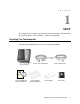
B-Series Touchcomputer User Guide B-Series LCD Multi-function Touchcomputer [15” and 17” model shown]
Tyco Electronics B-Series Touchcomputer User Guide Multi-function Touchcomputer Revision C P/N E610125 Tyco Electronics 1-800-ELOTOUCH (1-800-356-8682) www.elotouch.
Copyright © 2010 Tyco Electronics. All Rights Reserved. No part of this publication may be reproduced, transmitted, transcribed, stored in a retrieval system, or translated into any language or computer language, in any form or by any means, including, but not limited to, electronic, magnetic, optical, chemical, manual, or otherwise without prior written permission of Tyco Electronics Elo TouchSystems. Disclaimer The information in this document is subject to change without notice.
Table of Contents Chapter 1: Setup..................................................................................... 1 Unpacking Your Touchcomputer ....................................................................................................1 Adjusting the Display ......................................................................................................................2 Setting Up the Operating System......................................................................................
Chapter 6: Technical Support.............................................................. 41 Technical Assistance......................................................................................................................41 Regulatory Information ..........................................................................42 Warranty ..................................................................................................45 Index ............................................................
C H A P T E R 1 SETUP This chapter discusses how to set up and test your touchcomputer. For information on peripheral options, refer to Chapter 3, “Options and Upgrades.
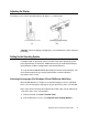
Adjusting the Display The display screen can be adjusted from 0 to 70 degrees, as shown below. 0° 70° CAUTION: To prevent tipping or dropping, be sure to hold the base when adjusting the display. Setting Up the Operating System If configured with an operating system, the initial setup of the operating system takes approximately 5-10 minutes. Additional time may be needed depending on touchcomputer hardware configurations and connected devices.
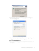
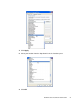
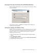
3. Click Customize. The Regional and Language Options window appears. Select the Languages tab. 4. If required, check the boxes for “Install files for complex script and right-to-left languages” and “Install files for East Asian languages.” 5. Select the Regional Options tab. 6. Select your preferred language from the drop-down list in the Standards and formats pane.
7. Click Apply. 8. Select your location from the drop-down list in the Locations pane. 9. Click OK.
Selecting the Time Zone (For Windows XP and POSReady 2009 Only) When the following window appears, you can change the time zone, date, and time of the touchcomputer. After making any changes, click Next to finish. Windows Setup completes the installation of the touchcomputer. Injecting the Languages (For Windows 7 Only) Windows 7 Professional only allows the use of one language at one time. But you can use the Elo TouchSystems language injection tool to update your language preference.
5. Click Inject, and the following window will pop out. 6. Click the drop-down list and select the preference language. 7. Click Inject Selected Language 8. The following window shall be presented.
9. After the language package is installed correctly, press any key to exit this window. 10. Click Exit Exit Restart Selecting the Region (For Windows 7 Only) When the following window appears, you can change the country, time and currency, and keyboard layout of the touchcomputer. After making any changes, click Next to continue.
Choosing the Computer Name (For Windows 7 Only) When the following window appears, you can choose a computer name of the touchcomputer. After making any changes, click Next to continue. Selecting the Update Options (For Windows 7 Only) When the following window appears, you can select one of the update options of the touchcomputer. In general, you can choose Use recommended settings as your default option.
After making any changes, click Next to continue. Reviewing the Time and Date Settings (For Windows 7 Only) When the following window appears, you can set up the time and date of the touchcomputer. After making any changes, click Next to finish. Windows Setup completes the installation of the touchcomputer. Calibrating the Touchscreen The touchscreen is pre-calibrated for accurate touch response.
Click the Align button. This launches the calibration program. The window shown below opens. Follow the instructions to calibrate the touchscreen.
Securing the Base When mounting the B-Series touchcomputer, the baseplate must be removed and mounted on a flat surface. Use the four pre-tapped holes to secure the baseplate from below the mounting surface before reattaching the touchcomputer as shown below. The holes are designed to work with ISO metric M6 screws. Mounting screws are not included with the product. Refer to the figure below for the location of the holes. All dimensions are in millimeters.
C H A P T E R 2 OPERATION This chapter describes how to control the On-Screen Display (OSD), power buttons, and I/O panel. All adjustments made to the OSD and power controls are automatically saved. User settings remain unchanged after powering off/on or in the case of a power failure.
On-Screen Display (OSD) OSD Menu 1. To display the OSD Menu, press the Menu button. Press the RIGHT button or LEFT button to toggle and the SELECT button to select from the different OSD sub-menus and functions. 2. When the function you want to change is shown, press the SELECT button. 3. To adjust the value of the function: 4. Pressing the RIGHT button increases the value of the selected OSD control option. 5. Pressing the LEFT button decreases the value of the selected OSD control option.
Feature Description Image setting Adjusts H position, V position, clock, and phase. • H position: Moves the screen horizontally right and left (1 pixel pitch increment). • V position: Moves the screen vertically up and down (1 line increment). • Clock: Adjusts the ratio of dividing frequency of the dot clock. • Phase: Adjusts the phase of the dot clock. Color Sets color temperature (9300K, 7500K, 6500K, 5500K, or User Preset). OSD Adjusts H position, V position, and OSD timeout.
L.E.D. Functionality The B-Series base has a LED indicating the state of the touchcomputer. The table below shows LED state and corresponding color.
Using the Input/Output Panel To access the input/output (I/O) ports, remove the cable cover at the bottom of the unit. A security screw is included and may be used to secure the cable cover to the touchcomputer. Below are the I/O descriptions by model: B1 and B3 models B2 models Note: The DB9 Serial (COM) ports are defaulted (from left to right) COM5 and COM6 Note: As a safety precaution, always leave the cable cover door attached when the system is powered on.
C H A P T E R 3 OPTIONS AND UPGRADES Adding Optional Peripherals When adding a peripheral, complete installation and setup instructions are provided with the field-installable kits.
Magnetic Stripe Reader (MSR) You can add a magnetic stripe reader (MSR) to the B-Series touchcomputer to any of the 4 mounting locations located on the display head top, bottom, left, and right. Software application and drivers can be found in the following directory or on www.elotouch.com C:\EloTouchSystems\SetupFiles\Peripherals The MSR is a USB 2.0 device that reads all three data stripes on standard credit cards or driver’s licenses conforming to ISO/ANSI standards.
Testing in USB MSR Human Interface Device (HID) Mode 1. Double-click the MagSwipe HID Demo icon to start the test application. 2. Slide a card through the MSR and verify that the data is displayed in the application window.
3. If the card ID appears in the Reader Output window, the reader is functioning. Customer Display You can optionally add a customer display to the B-Series touchcomputer to any of the four mounting locations located on the display head top, bottom, left, and right of the touchcomputer. Software application and drivers can be found at the following location www.elotouch.
Fingerprint Reader (FPR) You can add a fingerprint reader to the B-Series touchcomputer to any of the four mounting locations located on the display head top, bottom, left, and right. Software application and drivers can be found in the following directory or on www.elotouch.com C:\EloTouchSystems\SetupFiles\Peripherals The fingerprint reader is powered by the USB bus. The reader optically scans the fingerprint when the user touches the glowing window.
Powered USB + Cash Drawer Port Card A Powered USB + Cash Drawer Port Card can be installed in any available expansion slot. This card provides: • 2 x 12V Powered USB ports • 1 x 12V or 24V selectable cash drawer RJ11 port. The voltage setting can be set via jumper on the card prior to installing into the touchcomputer. Test applications can be found in the following directory or on www.elotouch.
C:\EloTouchSystems\SetupFiles\Peripherals Part number: E017487 Wireless Card A wireless adapter can be installed as an option in the B-Series touchcomputer in the I/O area under the cable cover. Typical specifications for the wireless card are: • USB dongle module • Compliant to USB 2.0 industry standards • IEEE 802.
Second Hard Disk Drive A second hard disk drive can be added via the second hard drive mounting kit. This addition provides extra data storage or can be used in conjunction with the RAID controller card for RAID functionality. This option occupies a single expansion slot. Part number: E109611 Solid State Drive A solid state drive can be added to (or used to replace) the original hard disk drive. This addition provides additional performance and more mechanically reliability in harsh environments.
Parallel Port Card A parallel port card can be added to any Expansion slot. This option provides a parallel port for printer interfaces only. Software drivers can be found in the following directory or on www.elotouch.com : C:\EloTouchSystems\SetupFiles\Peripherals Part number: E368899 Note: To use this option ALSO requires the purchase and installation of the Elo PCI-E Expansion Card Option Kit.
C H A P T E R 4 SAFETY AND MAINTENANCE Safety Important information regarding the proper setup and maintenance of your touchcomputer: • To reduce the risk of electric shock, follow all safety notices and never open the touchcomputer case. • Turn off the product before cleaning (refer to “Care and Handling” on page 30 for proper cleaning methods). • Your touchcomputer is equipped with a 3-wire, grounding power cord. The power cord plug only fits into a grounded outlet.
Care and Handling The following tips help keep your touchcomputer functioning at the optimal level. To avoid risk of electric shock, do not disassemble the power adapter or display unit cabinet. The unit is not user serviceable. Remember to unplug the display unit from the power outlet before cleaning. Do not use alcohol (methyl, ethyl, or isopropyl) or any strong solvent. Do not use thinner or benzene, abrasive cleaners, or compressed air.
WEEE Directive In the European Union, the Waste Electrical and Electronic Equipment (WEEE) directive label shown to the left indicates that this product should not be disposed of with household waste. It should be deposited at an appropriate facility for recovery and recycling. Recovering the Operating System If for any reason the touchcomputer’s operating system and software need to be recovered, there are two ways you can recover your system: i.
5. After finished, click Exit Exit System will restart automatically iii. Use the included image to recover the touchcomputer (For Windows 7 Only.) 1. After the TE logo shows up, press F8 (frequently) to enter Advanced Boot Options. 2. Select Repair your computer 3. Click Next OK (Shall not have password) Elo Touch System Tool 4.
5. Click Recover Start Recovery Process 6. After finished, click Exit Exit Restart NOTE: All data is deleted during the recovery process. The user must back up files when necessary. Elo TouchSystems does not accept liability for lost data or software. NOTE: If using POSReady 2009 or Windows 7 and your hard disk is corrupted, you can request a Recovery DVD from Elo TouchSystems customer service. NOTE: The end user must adhere to Microsoft's Licensing Agreement.
• Instructions to reassign the USB Serial Port 1. For Windows XP or POSReady 2009, right click the “Computer” Click “Properties” “Hardware” “Device Manager”. For Windows 7, right click the “Computer” Click “Properties” “Device Manager”.
2. Double click the “Ports (COM & LPT)” and check all of these “USB Serial Port” settings must be IDENTICAL as the following table. Description USB Serial Port (COM3) USB Serial Port (COM4) Location On USB Serial Converter A On USB Serial Converter B 3. If you see a situation as below, it shows the operating system has reassigned these serial ports. You need to correct it manually. In usual, even if the operating system reassigns these serial ports, they are still in order.
4. To correct it, please follow the instructions below: Double click the port you need to change. In this case, it is COM5. COM5 is the 1st port of these USB serial ports so the “Location:” should be “on USB Serial Converter A”. Please assign this serial port to COM3. (COM4 for the USB Serial Converter B).
Select “Port Settings” Click “Advanced…” In this case, select COM3 from the drop-down menu click OK OK back to the Device Manager. Follow the same steps to accomplish these settings for other ports.
After finished, right click on “Ports (COM & LPT)” and click Scan for hardware changes. 5. The outcome should be identical as the following diagram.
C H A P T E R 5 TECHNICAL SPECIFICATIONS Touchcomputer Specifications NOTE: FEATURE Not all operating systems or options are supported in all regions. Please contact your local Elo TouchSystems representative for details. B1 models B2 models Case/Bezel color B3 models Dark Grey Intel Celeron Dual Core E1500 2.2GHz Intel Atom Dual Core Intel Core 2 Duo D510 1.66GHz E8400 3.
Real-time Clock Replaceable lithium-ion battery for clock Controls Brightness, Contrast Phase Auto Adjust H-position, V-position Clock Sharpness RGB OSD H-Position, OSD V-Position OSD Time OSD Language (English, French, Italian, German, Spanish, Japanese, Simplified & Traditional Chinese) Recall Power button (All control buttons lockable) Display Languages 15” models - 15.0 in. diagonal, Active matrix TFT LCD, 4 x 3 17” models - 17.0 in.
LCD display 15.0-inch diagonal TFT active matrix LCD 17.0-inch diagonal TFT active matrix LCD 15” models - 0.297mm (H) x 0.297mm (V) Pixel Pitch 17” models - 0.264mm (H) x 0.264mm (V) Useful screen area 15” models - 304.128mm x 228.096mm Horizontal x Vertical 17” models - 337.920mm x 270.
15” models - 700:1 (typical) Contrast Ratio 17” models - 1000:1 (typical) 15” models 14 (W) x 14.3 (H) x 10.5 (D) in Maximum touchcomputer dimensions with stand 354.4(W) x 363.5(H) x 267.0(D) mm 17” models Display at 0° tilt (vertical) 15.2 (W) x 14.2 (H) x 10.5 (D) in 386.4 (W) x 361.0 (H) x 267.0 (D) mm 15” models 14.0 (W) x 13.1(H) x 3.6 (D) in 354.4 (W) x 331.8 (H) x 91.3(D) mm Maximum touchcomputer dimensions without stand 17” models 15.2 (W) x 13.0 (H) x 3.8 (D) in 386.4 (W) x 329.5 (H) x 95.
failures) Cables and Accessories North American and European Power cables included External 12VDC universal-type power supply brick Power Supply AC input voltage: 100-240V AC Input frequency: 50-60Hz Max output power: 240W Dimensional drawing number Mounting Options 15” models - MS600845 17” models - MS600846 1. With provided stand (on flat surface or bolted to surface via holes in base) in landscape or portrait mode 2.
C H A P T E R 6 TECHNICAL SUPPORT Technical Assistance There are three methods to obtain contact information for technical assistance on the touchcomputer: • The touchcomputer • The web • The phone Using the Touchcomputer You can access support information in System Properties by clicking the Support Information button. You can get to System Properties by either of the following methods: Right-click My Computer and choose Properties.
REGULATORY INFORMATION I. Electrical Safety Information A) Compliance is required with respect to the voltage, frequency, and current requirements indicated on the manufacturer’s label. Connection to a different power source than those specified herein may result in improper operation, damage to the equipment, invalidation of warranty, or a fire hazard if the requirements are not followed. B) There are no operator-serviceable parts inside this equipment.
C) Notice to Users in the European Union: Use only the provided power cords and interconnecting cabling provided with the equipment.
iv) Plug the digital device into a different AC outlet so the digital device and the receiver are on different branch circuits. v) Disconnect and remove any I/O cables that the digital device does not use. (Unterminated I/O cables are a potential source of high RF emission levels.) vi) Plug the digital device into only a grounded outlet receptacle. Do not use AC adapter plugs. (Removing or cutting the line cord ground may increase RF emission levels and may also present a lethal shock hazard to the user.
WARRANTY Except as otherwise stated herein or in an order acknowledgment delivered to Buyer, Seller warrants to Buyer that the Product shall be free of defects in materials and workmanship. With the exception of the negotiated warranty periods; the warranty for the touchcomputer and components of the product is 3 years. Seller makes no warranty regarding the model life of components. Seller’s suppliers may at any time and from time to time make changes in the components delivered as Products or components.
THESE REMEDIES SHALL BE THE BUYER’S EXCLUSIVE REMEDIES FOR BREACH OF WARRANTY. EXCEPT FOR THE EXPRESS WARRANTY SET FORTH ABOVE, SELLER GRANTS NO OTHER WARRANTIES, EXPRESS OR IMPLIED BY STATUTE OR OTHERWISE, REGARDING THE PRODUCTS, THEIR FITNESS FOR ANY PURPOSE, THEIR QUALITY, THEIR MERCHANTABILITY, THEIR NONINFRINGEMENT, OR OTHERWISE. NO EMPLOYEE OF SELLER OR ANY OTHER PARTY IS AUTHORIZED TO MAKE ANY WARRANTY FOR THE GOODS OTHER THAN THE WARRANTY SET FORTH HEREIN.
INDEX address, Elo TouchSystems, 49 software, 28 base power status, 15 mounting options, 11 base, securing, 11 on-screen display (OSD) enabling or disabling menu, 14 menu settings, 13 box contents, 1 cables included, 1 certifications, 44 operating system recovering, 28 setting up, 2 contact information, 41 operation, 12 controls, location diagram, 12 options, adding, 17 customer display overview, 20 specifications, 20 peripherals adding, 17 customer support, 41 ports accessing, 16 calibratio
technical specifications, 36 technical support, 41 time zone selection, 5, 7, 8, 9 touchscreen calibrating, 9 care and handling, 27 upgrades, adding, 17 warranty, 45 website, Elo TouchSystems, 41, 49 WEEE directive, 28 wireless card overview, 23 specifications, 23 testing, 23 www.elotouch.com Get the latest...
To find out more about Elo’s extensive range of touch solutions, visit our Website at www.elotouch.com or simply call the office nearest you: Elo TouchSystems 301 Constitution Drive Menlo Park, CA 94025 USA (800) ELO-TOUCH (800) 356-8682 Tel 650-361-4800 Fax 650-361-4747 customerservice@elotouch.com Europe Tyco Electronics Raychem B.V.B.A. (Elo TouchSystems Division) Diestsesteenweg 692 B-3010 Kessel-Lo Belgium Tel +32(0)(16)35 21 00 Fax +32(0)(16)35 21 01 elosales@elotouch.