Elo Entuitive Touchmonitor User Guide 15" LCD Desktop Touchcomputer ESY1525L/ESY1527L Touchcomputer Series Revision D P/N 008594 Elo TouchSystems, Inc. 1-800-ELOTOUCH www.elotouch.
Copyright © 2004 Elo TouchSystems Inc. All Rights Reserved. No part of this publication may be reproduced, transmitted, transcribed, stored in a retrieval system, or translated into any language or computer language, in any form or by any means, including, but not limited to, electronic, magnetic, optical, chemical, manual, or otherwise without prior written permission of Elo TouchSystems. Disclaimer The information in this document is subject to change without notice.
Table of Contents Chapter 1 Introduction Chapter 3 1 Safety/Servicing the Touchcomputer Precautions . . . . . . . . . . . . . . . . . . . . 1 About the Product . . . . . . . . . . . . . . . . . 1 Operating System . . . . . . . . . . . . . . . 2 Windows XP Pro and 2000 Pro . . . . . . . 2 Windows CE .Net Ver4.2 . . . . . . . . . . 2 Customer Display . . . . . . . . . . . . . . . 2 Magnetic Stripe Reader (MSR) . . . . . . . 2 Touchscreen . . . . . . . . . . . . . . . . 2 Drivers . . . . . . . . . . . . .
Altitude . . . . . . . . . . . . . . . . . . . . .
C H A P T E R INTRODUCTION CHAPTER1 Congratulations on your purchase of an Elo TouchSystems Entuitive Touchcomputer. This manual is to help you operate and maintain the Touchcomputer. Precautions Follow all warnings, precautions and maintenance as recommended in this user’s manual to maximize the life of your unit. See Appendix B for more information on touchmonitor safety.
mouse and an on screen keyboard to take the place of an external keyboard. The Touchcomputer provides the following options. Operating System A selection of operating systems can be made between Windows CE.Net Ver4.2, Windows XP Pro or Windows 2000 Pro. Windows XP Pro and 2000 Pro When Windows XP Pro and Windows 2000 Pro are selected, the Touchcomputer will have a 20 GB or greater hard drive and 256 MB of SDRAM. The Touchcomputer will boot from the hard drive, which contains the operating system.
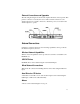
External Connections and Upgrades The following drawing shows the Touchcomputer External connector panel. This panel of connectors is used by the user to make external connections to the Touchcomputer. No external connections, other than power, are needed for the Touchcomputer to operate.
Keyboard • A keyboard can be added using the keyboard port. Upgrades and Changes A laptop type hard drive (2.5") can be added internally to the CE version of the Touchcomputer. • SDRAM can be increased from the standard 256 M to 512 M • Compact Flash can be added (through the compact flash door in the back of the Touchcomputer) to the Touchcomputer on Windows XP Pro and Windows 2000 Pro Touchcomputers. • Customer Displays and Magnetic Stripe Readers can added to any Touchcomputer.
• US Power Cable • European Power Cable • Power Brick • Applicable Operating System CD • Windows 2000 Pro • Windows XP Pro • No CD is provided for Windows CE.Net Ver4.2 (but the image is on the Touchcomputer CD.
Models The Touchcomputer is available in the following models. A key at the end of the model list explains the options.
Key PIP Description Key ESY = Elo System 15 = 15 Inch Display 25 = Desktop cabinetry (In grey plastics only) L = LCD 7 = AccuTouch 8 = IntelliTouch S = Serial controller U = USB controller W = Worldwide agencies A = Revision number 1 = Antiglare glass Mx = MSR unit x = 2 = MSR USB HID x = 3 = MSR USB Keyboard Emulation Cx = Customer Display x = 1 = Serial Customer Display CE = Windows CE.Net 4.
1-8 Elo Entuitive Touchmonitor User Guide
C H A P T E R Touchcomputer SETUP CHAPTER2 Initial Turn On and Software Registration Touchcomputer Operating System Setup The initial setup of the Windows operating system takes approximately 5-10 minutes. Additional time may be needed depending on computers hardware configuration and connected devices. To setup the Windows OS for you computer, turn on your computer and follow the instructions on the screen. The Touchcomputer should be connected to a network providing an internet connection.
Computer Reboots • Wait for computer to reboot and finally boot up to the desktop. Testing Pre-installed Devices Touchcomputer come pre installed with several different hardware options. To test these options, click on the following icons on the Windows toolbar on the bottom right of the computer. You may also use the desktop icons. Customer Display Testing • Click on the “CD” icon. • The customer display should change, now displaying the text “Elo TouchSystems Customer Display”.
Touchcomputer Controls Switch 1 Switch 2 Switch 3 Switch 4 Switch 5 Power To turn power off, press and hold switch 5. To turn on press and hold switch 5 then shut down. To do a hard shutdown, press and hold switch 5. To turn power on, press the power button once.
Power and OSD Lock Out Normally the 5 switches on the side of the monitor depicted in the figure in the controls section control power, brightness and volume. The power switch can be made not to operate by activating the power lockout function. The brightness and volume adjustment can be made not to operate by activing the OSD lockout function. The OSD lockout function can be a activate by simultaneously pressing Switch 1 and Switch 2.
C H A P T E R SAFETY/SERVICING THE Touchcomputer CHAPTER3 When servicing the computer perform the following: • Perform an orderly shutdown using the operating system menu. • Shut down the Touchcomputer and remove all external cables. • When opening the Touchcomputer, periodically touch any metal parts of the Touchcomputer, such as metal portions of the case or connector shells on the monitor. • Handle components and cards with care. Do not touch components on the cards.
3-14 Elo Entuitive Touchmonitor User Guide
C H A P T E R TECHNICAL DESCRIPTION CHAPTER4 Block Diagram The block diagram of the Touchcomputer is shown below: Elo Touchcomputer Block Diagram LCD J11 +12 VDC USB2 Dual USB Port(500 ma) CN13 Serial Port CN14 Serial Port J16 OSD Switch panel CN10 Dual USB Port(500 ma) CN7 Speakers Inveter USB1 Optional Hard Drive CN11 J7 Optional Compact Flash J17 PS2 keyboard PS2 keyboard J12 PCMCIA J15 Ethemet Port CN5 Mother board CN1 CN9 Serial Port USB Port Optional MSR CN3 Inte
Mother Board Block Diagram MEMORY PC133/SDR VIA EDEN ESP 600 MHZ PROCESSOR FSB BOOT ROM VIA VT8606 TWISTER NORTHBRIDGE GRAPHICS CORE AND MEMORY CONTROLLER REALTEK RTL8100C FAST ETHERNET CONTROLLER PCI VIA VT82C686B SOUTHBRIDGE PERIPHERAL CONTROLLER FAST ETHERNET SOUND KEYBOARD MOUSE HARD DRIVE 2 SERIAL PORTS 4 USB PORTS LCD DISPLAY 4-16 Elo Entuitive Touchmonitor User Guide WINDBOND W83977F I/O CONTROLLER 2 SERIAL PORTS TI PCI1410 PC CARD CONTROLLER PCMCIA
Connectors on Mother Board The connectors on mother board allows you to connect external devices such as keyboard, floppy disk drives, hard disk drives, printers, etc. The following table lists the connectors on mother board and their respective functions.
CN1, CN2: COM4 and COM3 Connectors Pin # Signal Name 1 DCD 2 RXD 3 CTS 4 GND 5 TXD 6 RTS 7 DSR 8 DTR CN3: +5V Connector Pin # Signal Name 1 +5V 2 Ground CN4: +5V AND +12V Connector Pin # Signal Name 1 +5V 2 Ground 3 +12V CN6, CN9: USB Pin Header Pin # Signal Name 1 Ground 2 USB3 USB+ 4 Vcc CN10: Panel Inverter Power Connector Pin # 1 2 3 4 5 Signal Name +12V Ground Bright Adj Ground BKLT ON CN11: OSD Panel Board Connector Pin # Signal Name 1 Vol+ 2 Vol3 Bright+ 4 Bright5 Ground 6 Power On/Off 4-18 Elo En
J7: Primary IDE Connectors Pin # Pin # Signal Name 1 3 5 7 9 11 13 15 17 19 21 23 25 27 29 31 33 35 37 39 41 43 2 4 6 8 10 12 14 16 18 20 22 24 26 28 30 32 34 36 38 40 42 44 Ground Host data 8 Host data 9 Host data 10 Host data 11 Host data 12 Host data 13 Host data 14 Host data 15 Key Ground Ground Ground Host ALE Ground No connect No connect ASDRAMess 2 Chip select 1 Ground Vcc N.C.
USB1, USB2: USB Connectors Pin # Signal Name 1 Vcc 2 USB3 USB+ 4 Ground J9: System Fan Power Connector J9 is a 3-pin header for an optional fan. The fan must be a 12V fan. Pin # Signal Name 1 Ground 2 +12V 3 Rotation detection J11: 24-bit LVDS Connector (DF13-20) Signal Name TX0Ground TX15V/3.3V TX3TX2Ground TXC5V/3.
J16: PS/2 Keyboard Connector 6 5 4 3 1 2 Pin 1 2 3 4 5 6 Signal Name Keyboard data N.C. GND 5V Keyboard clock N.C. J17: PS/2 Mouse Connector Pin Signal Name 6 5 1 Mouse data 2 N.C. 4 3 3 GND 2 1 4 5V 5 Mouse clock 6 N.C.
Computer Specifications Processor • VIA Eden 600MHz low power CPU or equivalent Memory • RAM- 256 MB expandable to 512 MB Green Function • APM 1.2 compliant Audio Function • Stereo one watt capability per channel Operating System • Support for WinCE.Net Ver4.2 • Support for Windows 2000 Pro • Support for Windows Xp Pro Ports • Four RS-232 Serial Ports. Two internal ports(CN2 and CN1) and 2 external ports (CN13 and CN14). • Connectors-External ports shall use standard DB9 connectors.
• One Compact Flash Socket (CN5) • One hard drive socket located on the bottom of the board (J7) Real Time Clock • Battery backed up real time clock that features a multi-century calendar. • Lithium battery with socket. • On Screen Display • Volume Control • Backlight Brightness Windows CE.Net Ver4.2 Board Support Package A board support package is available to assist users with custom software development.
Display The LCD display consists of an LCD, inverter, and OSD switch module. The performance of the LCD display will be: Display Size Native Resolution Display Color Number Display Type Typical Contrast Ratio Typical/Min Brightness Typical Display Speed Typical Vertical Viewing Angle Typical Horizontal Viewing Angle Chromaticity 4-24 15.0 diagonal 1024 x 768 pixels 16.
TABLE 1. Chromaticity Symbol Chromaticity of White Chromaticity of Red Chromaticity of Green Chromaticity of Blue Wx Wy Rx Ry Gx Gy Bx By Values Minimum 0.282 0.288 0.613 0.314 0.274 0.536 0.111 0.055 Typical 0.312 0.318 0.6437 0.344 0.304 0.566 0.141 0.085 Maximum 0.342 0.348 0.673 0.374 0.334 0.596 0.171 0.115 Touchscreen Assembly The touchscreen assembly consists of a touchscreen and a controller.
Customer Display The Customer Display is a twenty character two line vacuum fluorescent display (VFD). It consists of a VFD and VFD controller. There is a serial version controller and a USB controller. The actual VFD is common to the serial and USB versions. CE will only use the serial as no CE USB driver is available. Optical Parameters Characters per row Number of rows Character configuration Character Height Character width Character configuration Character color MTBF 20 2 5x7 dot matrix 9.5 mm 6.
Specifications Reference Standards Conform to applicable standards Power Input Message Format Card Speed MTBF Operating Current Suspend current Length Width International Standards Organization, American National Standards Institute, California Drivers License, American Association of Motor Vehicle Administrators From USB port ACCII 3 to 50 IPS Electronics 125,000 hrs; Head 1,000,000 passes 30 ma max 300 ua max 100 mm 32.
4-28 Elo Entuitive Touchmonitor User Guide
C H A P T E R Touchcomputer COMPONENT LAYOUT CHAPTER5 The figures below show the complete Touchcomputer identifying the major components discussed in Chapter 1.
Touchcomputer Assembly 5-30 Elo Entuitive Touchmonitor User Guide
Touchcomputer Exploded View CHAPTER5 5-31
5-32 Elo Entuitive Touchmonitor User Guide
C H A P T E R COMPONENTS CHAPTER6 External 12 VDC Power Supply The Touchcomputer is powered by 12 VDC from a universal type power supply brick. The power supply shall provide the following capability: • Input voltage 85 to 263 vac • Input frequency 47 to 63 hz • Output voltage 12 vdc • Output line and load regulation +/- 2% Memory and Hard Drive Options Windows 2000 Pro and Windows XP Pro • Hard Drive Provided, 20GB or higher • 256 MB provided • No compact flash provided Windows CE.Net Ver4.
Cables External Cables The following cables will be included: • US power cable for the external power supply • European power cable for the external power supply • Power cable from the 12 VDC external supply to the Touchcomputer. All cables are 6 feet long.
C H A P T E R ENVIRONMENTAL REQUIREMENTS CHAPTER7 Temperature Ranges Operating Temperature (Independent of altitude) Non-Operating Temperature (Independent of altitude) 0° to 40° -30° to 60° Humidity Operating (non-condensing) Non-Operating (38.7°C max. wet bulb temperature) 20% to 80% 5% to 95% Altitude Operating 0 to + 12,000 feet [3,658m]. Non-Operating 0 to + 40,000 feet [12,192m]. Equivalent to 14.7 to 10.1 psia. Equivalent to 14.7 to 4.4 psia.
7-36 Elo Entuitive Touchmonitor User Guide
REGULATORY INFORMATION CHAPTER0 I. Electrical Safety Information: A) Compliance is required with respect to the voltage, frequency, and current requirements indicated on the manufacturer’s label. Connection to a different power source than those specified herein will likely result in improper operation, damage to the equipment or pose a fire hazard if the limitations are not followed. B) There are no operator serviceable parts inside this equipment.
This Information Technology Equipment (ITE) is required to have a CE Mark on the manufacturer’s label which means that the equipment has been tested to the following Directives and Standards: This equipment has been tested to the requirements for the CE Mark as required by EMC Directive 89/336/EEC indicated in European Standard EN 55 022 Class B and the Low Voltage Directive 73/23/EEC as indicated in European Standard EN 60 950.
"The application of this monitor is restricted to special controlled luminous environments. The screen surface trend to reflect annoying light of lamps and sunlight. To avoid these reflections the monitor should not be positioned in front of a window or directed to luminaries. The monitor is in compliance with Reflection Class III according to ISO 13406-2" "Die Anwendung dieses Bildschirms ist auf speziel kontrollierte Umgebungsbeleuchtungen eingeschränkt.
40 Elo Entuitive Touchmonitor User Guide
WARRANTY CHAPTER0 Except as otherwise stated herein or in an order acknowledgment delivered to Buyer, Seller warrants to Buyer that the Product shall be free of defects in materials and workmanship. The warranty for the touchcomputer and components of the product is 1 year. Seller makes no warranty regarding the model life of components. Seller’s suppliers may at any time and from time to time make changes in the components delivered as Products or components.
THESE REMEDIES SHALL BE THE BUYER’S EXCLUSIVE REMEDIES FOR BREACH OF WARRANTY. EXCEPT FOR THE EXPRESS WARRANTY SET FORTH ABOVE, SELLER GRANTS NO OTHER WARRANTIES, EXPRESS OR IMPLIED BY STATUTE OR OTHERWISE, REGARDING THE PRODUCTS, THEIR FITNESS FOR ANY PURPOSE, THEIR QUALITY, THEIR MERCHANTABILITY, THEIR NONINFRINGEMENT, OR OTHERWISE. NO EMPLOYEE OF SELLER OR ANY OTHER PARTY IS AUTHORIZED TO MAKE ANY WARRANTY FOR THE GOODS OTHER THAN THE WARRANTY SET FORTH HEREIN.
INDEX A About the Product, 1 Accessory Kit, 4 Altitude, 35 Audio Function, 22 B Block Diagram, 15 C Cables, 28 CD/DVD Drives, 3 Chromaticity, 18 Computer Reboots, 10 Computer Specifications, 22 Controls, 10 Customer Display, 2, 26 Customer Display Testing, 10 D Display, 24 Display Color Number, 24 Display Size, 24 Display Type, 24 Drivers, 2 E External 12 VDC Power Supply, 25, 33 External Cables, 34 External Connections, 3 External Connections and Upgrades, 3 G Keyboard Card Reader Testing, 10 L Lice
Testing Pre-installed Devices, 10 Touch Tool CD, 4 Touchscreen, 2 Touchscreen Assembly, 25 Typical Contrast Ratio, 24 Typical Display Speed, 24 Typical/Min Brightness, 24 U Upgrades and Changes, 4 USB Card Reader Testing, 10 USB MSR, 26 Using the Phone, Technical Assistance, 12 Using the Touchcomputer, Technical Assistance, 12 Using the Web, Technical Assistance, 12 V Vertical Viewing Angle, 18 W Warranty, 37 Windows 2000 Pro and Windows XP Pro, 33 Windows CE.Net Ver4.2, 2 Windows CE.Net Ver4.
Check out Elo's Web site! www.elotouch.com Get the latest... • Product information • Specifications • News on upcoming events • Press releases • Software drivers Getting in Touch with Elo To find out more about Elo’s extensive range of touch solutions, visit our Web site at www.elotouch.com or simply call the office nearest you: (800) ELO-TOUCH (800-356-8682) Tel 650-361-4700 Fax 650-361-4747 eloinfo@elotouch.com Germany Elo TouchSystems GmbH & Co.
Elo Entuitive Touchcomputer Benutzerhandbuch 15"-LCD-Desktop-Touchcomputer Touchcomputer-Serie ESY1525L/ESY1527L Revision D Teile-Nr. 008594 Elo TouchSystems, Inc. 1-800-ELOTOUCH www.elotouch.
Copyright © 2004, Elo TouchSystems Inc. Alle Rechte vorbehalten. Jede Vervielfältigung, Übertragung, Abschrift, elektronische Speicherung sowie Übersetzung dieses Dokumentes in irgendeine Sprache oder Computersprache ist in jeder Form und unter Zuhilfenahme jeglicher elektronischer, magnetischer, optischer, chemischer, manueller oder sonstiger Mittel untersagt und bedarf der ausdrücklichen schriftlichen Genehmigung durch Elo TouchSystems.
iv
Inhaltsverzeichnis Kapitel 1 Kapitel 3 Einführung Vorsichtsmaßnahmen . . . . . . . . . . . . Hinweise zum Produkt. . . . . . . . . . . . Betriebssystem . . . . . . . . . . . . . . Windows XP Pro und 2000 Pro . . . . Windows CE.Net Version 4.2 . . . . . Kunden-Display . . . . . . . . . . . . . Magnetstreifenleser (MSR) . . . . . . Touchscreen (Tastbildschirm) . . . . . Treiber. . . . . . . . . . . . . . . . . Externe Verbindungen und Upgrades. Externe Verbindungen . . . . . . . . . .
Copyright © 1996, Borland International. All rights reserved. BORLAND CONFIDENTIAL October 18, 2004 5:14 pm (C:\Documents and Settings\SandyW\My Documents\My Documents\!Client\Ongong\EL43946 - ELO\German\Frame\1X8XC_2187CTOC.fm) Kapitel 7 Umgebungsanforderungen 39 Temperatur . . . . . . . . . . . . . . . . . . . 39 Feuchtigkeit . . . . . . . . . . . . . . . . . . . 39 Höhe. . . . . . . . . . . . . . . . . . . . . . .
K A P I T E L 1 EINFÜHRUNG CHAPTER1 Wir beglückwünschen Sie zum Kauf eines Elo TouchSystems EntuitiveTouchcomputers. Dieses Handbuch soll Ihnen beim Bedienen und Warten des Touchcomputers behilflich sein. Vorsichtsmaßnahmen Befolgen Sie alle Warnungen, Sicherheitshinweise und Wartungsempfehlungen in diesem Handbuch, um eine möglichst lange Lebensdauer des Geräts zu gewährleisten. Sicherheitshinweise zum Touchmonitor finden Sie in Anhang B.
Tastatur kann die auf dem Bildschirm angezeigte Tastatur verwendet werden. Im Folgenden werden die Optionen des Touchcomputers erläutert. Betriebssystem Es kann zwischen den Betriebssystemen Windows CE.Net Version 4.2, Windows XP Pro und Windows 2000 Pro ausgewählt werden. Windows XP Pro und 2000 Pro Bei Verwendung des Betriebssystems Windows XP Pro oder Windows 2000 Pro verfügt der Touchcomputer über eine Festplatte mit 20 GB oder mehr sowie 256 MB SDRAM.
Treiber Jedem System sind entsprechende Treiber und Testprogramme beigefügt, die das Funktionieren aller gewählten Optionen gewährleisten. Externe Verbindungen und Upgrades In der nachstehenden Abbildung ist die externe Anschlussblende des Touchcomputers dargestellt. An der Anschlussblende stellt der Benutzer die äußeren Verbindungen des Touchcomputers her. Die Spannungsversorgung ist die einzige externe Verbindung, die für den Betrieb des Touchcomputers erforderlich ist.
Festplatte für Version CE Eine zusätzliche Festplatte für Touchcomputer der Version CE kann entweder am USB-Eingang angeschlossen oder im Gerät eingebaut werden. Maus Für den Anschluss einer Maus steht ein eigener Anschluss zur Verfügung. Tastatur • Für den Anschluss einer Tastatur steht ein eigener Anschluss zur Verfügung. Upgrades und Änderungen Bei einem Touchcomputer der Version CE kann zusätzlich eine 2,5"-LaptopFestplatte eingebaut werden.
Zubehör-Kit Jeder Monitor wird mit einem Zubehör-Kit geliefert. Zum Umfang des Zubehör-Kits gehört Folgendes: • CD „Touchtool“ - Diese enthält die Treiber und das Handbuch für Touchscreen-Produkte von EloTouch. Die Touchscreen-Treiber sind auf dem Touchcomputer bereits vorinstalliert. Die Treiber auf der CD-ROM sind für eine eventuelle Neuinstallation des Betriebssystems vorgesehen.
Modelle Nachstehend sind die Modelle des Touchcomputers aufgeführt. Die Optionen sind am jeweiligen Schlüssel erkennbar und werden am Ende der Liste erläutert.
Schlüssel PIP-Schlüssel (Beschreibung) ESY = Elo-System 15 = 15-Zoll-Bildschirm 25 = Desktop-Kabinett (nur bei grauem Kunststoffgehäuse) L = LCD 7 = AccuTouch 8 = IntelliTouch S = Serieller Controller U = USB-Controller W = Vertretungen weltweit A = Revisionsnummer 1 = Entspiegeltes Glas Mx = Magnetstreifenleser (MSR) x = 2 = USB-HID für Magnetstreifenleser x = 3 = USB-Tastaturemulation für Magnetstreifenleser Cx = Kunden-Display x = 1 = Serielles Kunden-Display CE = Windows CE.Net Version 4.
10 Elo Entuitive Touchmonitor Benutzerhandbuch
K A P I T E L 2 EINRICHTEN DES TOUCHCOMPUTERS CHAPTER2 Inbetriebnahme und Software-Registrierung Einrichten des Betriebssystems Das erste Einrichten des Windows-Betriebssystems dauert ca. fünf bis zehn Minuten. Abhängig von der Konfiguration der Computerhardware und den angeschlossenen Geräten ist mit einem zusätzlichen Zeitaufwand zu rechnen. Um das Windows-Betriebssystem auf ihrem Computer einzurichten, müssen Sie den Computer einschalten und den Anweisungen auf dem Bildschirm folgen.
Netzwerkeinstellungen • Warten Sie, bis das Windows-Betriebssystem die Netzwerkeinstellungen konfiguriert hat. Letzte vorbereitende Schritte • Warten Sie, bis das Windows-Betriebssystem die Netzwerkeinstellungen konfiguriert hat. Computer neu starten • Warten Sie, bis der Computer neu startet und der Desktop angezeigt wird. Testen vorinstallierter Hardware Der Touchcomputer wird mit verschiedenen vorinstallierten Hardwareoptionen geliefert.
Bedienelemente Für die Bedienung des Touchcomputers stehen zwei Bedienelemente zur Verfügung. Es gibt einen Helligkeitsregler und einen Lautstärkeregler. Um die Helligkeit zu erhöhen, drücken Sie Schalter 3. Wenn Sie die Helligkeit verringern möchten, drücken Sie Schalter 4. Um die Lautstärke anzuheben, drücken Sie Schalter 1. Wenn Sie die Lautstärke verringern möchten, drücken Sie Schalter 2. Touchcomputer-Bedienelemente Netzschalter Um das Gerät abzuschalten, halten Sie den Schalter 5 gedrückt.
Netzschalter- und OSD-Sperre Normalerweise dienen die fünf Schalter an der Seite des Monitors (s. Abbildung unter „Bedienelemente“) zum Ein- und Ausschalten des Geräts sowie zum Regeln der Helligkeit und Lautstärke. Durch Aktivieren der Netzschalter-Sperrfunktion lässt sich der Netzschalter außer Kraft setzen. Durch Aktivieren der OSD-Sperrfunktion lässt sich die Helligkeits- und Lautstärkeregelung außer Kraft setzen. Die OSD-Sperrfunktion wird durch gleichzeitiges Drücken von Schalter 1 und 2 aktiviert.
Über das Internet www.elotouch.com/support/default.asp Über das Telefon Die Nummer der Kundenunterstützung lautet +1-800-557-1458. Ihr Anruf ist kostenfrei.
16 Elo Entuitive Touchmonitor Benutzerhandbuch
K A P I T E L 3 SICHERHEITS- UND WARTUNGSHINWEISE CHAPTER3 Bei der Wartung des Computers sind folgende Schritte durchzuführen: • Fahren Sie das Gerät ordnungsgemäß über das Menü des Betriebssystems herunter. • Schalten Sie den Touchcomputer aus, und entfernen Sie alle externen Kabel. • Wenn Sie den Touchcomputer öffnen, sollten Sie diesen hin und wieder an irgendwelchen metallischen Oberflächen wie z. B. dem Gehäuse oder einer Steckerhülse berühren.
18 Elo Entuitive Touchmonitor Benutzerhandbuch
K A P I T E L 4 TECHNISCHE BESCHREIBUNG CHAPTER4 Blockdiagramm Nachstehend ist der Touchcomputer in einem Blockdiagramm dargestellt: Elo Touchcomputer - Blockdiagramm 19
Motherboard - Blockdiagramm 20 Elo Entuitive Touchmonitor Benutzerhandbuch
Motherboard - Anschlüsse An den Anschlüssen des Motherboards können Sie externe Geräte wie Tastatur, Disketten- und Plattenlaufwerke, Drucker usw. anschließen. In der folgenden Tabelle sind diese Anschlüsse mit ihren jeweiligen Funktionen aufgeführt.
CN1, CN2: Anschlüsse COM4 und COM3 Pin-Nr. 1 2 3 4 5 6 7 8 Belegung DCD RXD CTS GND TXD RTS DSR DTR CN3: 5-V-Anschluss (+) Pin-Nr. 1 2 Belegung +5 V Masse CN4: 5-V- und +12-V-Anschluss (+) Pin-Nr. 1 2 3 Belegung +5 V Masse +12 V CN6, CN9: USB-Stiftsockel Pin-Nr. 1 2 3 4 Belegung Masse USBUSB+ Vcc CN10 Vcc: Stecksockel Inverter-Spannungsversorgung (Anschlussleiste) Pin-Nr. 1 2 3 4 22 Belegung +12 V Masse Helligk.-Einst. Hintergrundbel.
CN11: OSD-Stecksockel (Anschlussleiste) Pin-Nr. 1 2 3 4 5 6 Belegung Lauter Leiser Heller Dunkler Masse Netz Ein/Aus J7: IDE-Hauptanschlüsse Belegung IDE-Reset Host-Daten 7 Host-Daten 6 Host-Daten 5 Host-Daten 4 Host-Daten 3 Host-Daten 2 Host-Daten 1 Host-Daten 0 Masse DRQ0 Host IOW Host IOR IOCHRDY DACK0 IRQ14 ASDRAMess 1 ASDRAMess 0 Chip-Auswahl 0 Aktivität Vcc Masse Pin-Nr. 1 3 5 7 9 11 13 14 17 19 21 23 25 27 29 31 33 35 37 39 41 43 Pin-Nr.
FDD1: Anschluss für Diskettenlaufwerk FDD1 ist ein schmaler, 26-poliger Sockel, der Diskettenlaufwerke mit bis zu 2,88 MB unterstützt. Belegung VCC VCC VCC NC NC DINST NC GND GND GND NC GND GND Pin-Nr. 1 3 5 7 9 11 13 14 17 19 21 23 25 Pin-Nr. 2 4 6 8 10 12 14 16 18 20 22 24 26 Belegung INDEX DRV_SEL DSK_CH NC MOTOR DIR STEP WDATA WGATE TRACK WPROT RDATA SIDE USB1, USB2: USB-Anschlüsse Pin-Nr.
J11: 24-Bit-LVDS-Anschluss (DF13-20) Belegung TX0Masse TX15 V/3,3 V TX3TX2Masse TXC5 V/3,3 V 12 V (+) Pin-Nr. 2 4 6 8 10 12 14 16 18 20 Pin-Nr. 1 3 5 7 9 11 13 15 17 19 Belegung TX0+ Masse TX1+ Masse TX3+ TX2+ Masse TXC+ ENABKL 12 V (+) J13: VGA-Monitoranschluss J13 ist ein 8-poliger Sockel für einen optionalen externen („weiblichen“) VGA-Monitoranschluss. Belegung Rot Grün Blau nicht belegt Masse Masse Masse Masse Pin-Nr. 1 3 5 7 9 11 13 15 Pin-Nr.
J16: PS/2-Tastaturanschluss Pin-Nr. 1 2 3 4 5 6 Belegung Tastaturdaten nicht belegt GND (Masse) 5V Uhr (Tastatur) nicht belegt J17: PS/2-Mausanschluss Pin-Nr.
Computerspezifische Angaben Prozessor • CPU - VIA Eden, 600 MHz Niederspannung oder gleichwertig Hauptspeicher • RAM - 256 MB, erweiterbar auf 512 MB Energiesparfunktion • APM 1.2-konform Audiofunktion • Stereo, Leistung 1 Watt pro Kanal Betriebssystem • Unterstützung für WinCE.Net Version 4.2 • Unterstützung für Windows 2000 Professional • Unterstützung für Windows XP Professional Anschlüsse • Vier serielle Anschlüsse RS-232, zwei interne (CN2, CN1) sowie 2 externe Anschlüsse (CN13, CN14).
• PS2-Tastatur (J16) • PS2-Maus (J17) • Eine Compact Flash-Buchse (CN5) • Ein Festplattensockel an der Unterseite der Platine (J7) Echtzeituhr • Batteriegesicherte Echtzeituhr mit jahrhundertübergreifender Kalenderfunktion. • Lithiumbatterie mit Fassung. • OSD (On Screen Display) • Lautstärkeregler • Hintergrund-Helligkeit Board Support Package für Windows CE.Net Version 4.2 Zur Unterstützung des Benutzers mit individuellen Software-Entwicklungen steht ein Board Support Package zur Verfügung.
• PS2-Tastaturanschluss (ohne Tastatur) • PS2-Mausanschluss (ohne Maus) • Netzspannungsversorgung • PCMCIA-Steckplatz mit Auswurftaste • Compact Flash Anzeige Der LCD-Bildschirm besteht aus einer Einheit mit LCD-Anzeige, Inverter und OSD-Schalter.
TABELLE 1. Farbortwerte Symbol Minimal Typisch Maximal Farbort Weiß Wx Wy 0.282 0.288 0.312 0.318 0.342 0.348 Farbort Rot Rx Ry 0.613 0.314 0.6437 0.344 0.673 0.374 Farbort Grün Gx Gy 0.274 0.536 0.304 0.566 0.334 0.596 Farbort Blau Bx By 0.111 0.055 0.141 0.085 0.171 0.115 Touchscreen-Einheit Die Touchscreen-Einheit besteht aus dem Tastbildschirm und einem Controller.
Kunden-Display Das Kunden-Display ist ein VFD (Vacuum Fluorescent Display) mit zwanzig Stellen in zwei Zeilen. Es besteht aus der VFD-Einheit und dem VFD-Controller. Neben dem seriellen Versions-Controller steht ein USB-Controller zur Verfügung. Das eigentliche VFD ist sowohl auf die serielle als auch auf die USB-Version abgestimmt. Bei der CE-Ausführung wird nur die serielle Version verwendet, da kein CE USB-Treiber verfügbar ist.
Technische Daten 32 Referenz-Standards Gemäß zutreffenden Standards ISO (International Standards Organization), ANSI (American National Standards Institute), California Drivers License, American Association of Motor Vehicle Administrators Spannungsversorgung über USB-Anschluss Nachrichtenformat ACCII Kartengeschwindigkeit 3 bis 50 IPS MTBF Elektronik 125.000 Std., Kopf 1.000.000 Durchgänge Betriebsstrom max. 30 mA Ruhestrom max. 300 µA Länge 100 mm Breite max.
K A P I T E L 5 ANORDNUNG DER KOMPONENTEN CHAPTER5 Nachstehend finden Sie eine grafische Gesamtansicht des Touchcomputers mit den wesentlichen in Kapitel 1 beschriebenen Bauteilen.
Aufbau des Touchcomputers 34 Elo Entuitive Touchmonitor Benutzerhandbuch
Explosionsansicht 35
36 Elo Entuitive Touchmonitor Benutzerhandbuch
K A P I T E L 6 KOMPONENTEN CHAPTER6 Externes Netzteil (12 VDC) Die Spannungsversorgung (12 VDC) erfolgt über ein universelles externes Netzteil. Leistungsvoraussetzungen: • Eingangsspannung 85 bis 263 VAC • Eingangsfrequenz 47 bis 63 Hz • Ausgangsspannung 12 VDC • Ausgangstoleranz +/- 2 % Hauptspeicher- und Festplattenoptionen Windows 2000 Pro und Windows XP Pro • Plattenlaufwerk vorhanden, 20 GB oder mehr • 256 MB vorhanden • Kein Compact Flash Windows CE.Net Version 4.
Netzkabel Externe Kabel Folgende Kabel sind im Lieferumfang enthalten: • Netzkabel (USA) für externe Spannungsversorgung • Netzkabel (Europa) für externe Spannungsversorgung • Verbindungskabel vom externen Netzteil (12 VDC) zum Touchcomputer. Alle Kabel sind ca. 2 Meter lang.
K A P I T E L 7 UMGEBUNGSANFORDERUNGEN CHAPTER7 Temperatur Betriebstemperatur (höhenunabhängig) Im Ruhezustand (höhenunabhängig) 0 bis +40 °C -30 bis +60 °C Feuchtigkeit Im Betrieb (nicht kondensierend) Im Ruhezustand 5 bis 95 % (bei einer Messtemperatur von max. 38,7 °C) 20 bis 80 % 5 bis 95 % Höhe Im Betrieb 0 bis 3.658 m Im Ruhezustand 0 bis 12.192 m (entspricht 14,7 bis 10,1 psi.a.) (entspricht 14,7 bis 4.4 psi.a.
40 Elo Entuitive Touchmonitor Benutzerhandbuch
HINWEISE ZUR HANDHABUNG CHAPTER7 I. Sicherheitshinweise zur Elektrik: A) Die auf dem Etikett des Herstellers angegebenen Anforderungen bezüglich Spannung, Frequenz und Stromstärke müssen erfüllt sein. Bei Nichtbeachtung der in dieser Dokumentation genannten Anforderungen und Einschränkungen hinsichtlich der zu verwendenden Spannungsquelle ist mit einem fehlerhaften Betrieb oder einer Beschädigung der Gerätschaften bis hin zur Brandauslösung zu rechnen.
Dieses Gerät ist als ITE (Information Technology Equipment) eingestuft und muss auf dem Etikett des Herstellers mit dem CE-Zeichen versehen sein, um darauf hinzuweisen, dass es gemäß folgender Vorschriften und Standards geprüft wurde: Dieses Gerät wurde hinsichtlich der CE-Anforderungen gemäß EMC-Vorschrift 89/336/EG zur elektromagnetischen Verträglichkeit gemäß Euro-Norm EN 55 022, Klasse B, und der Vorschrift 73/23/EG für Niederspannungsgeräte gemäß Euro-Norm EN 60 950 getestet.
vi) Schließen Sie das Digitalgerät nur an eine geerdete Steckdose an. Verwenden Sie keinen Wechselstromstecker. (Das Entfernen oder Durchtrennen des Anschlusskabels kann eine Erhöhung des Störgeräuschpegels sowie u. U. einen Stromstoß mit tödlichen Folgen verursachen.) Sollten Sie weitere Hilfe benötigen, wenden Sie sich an Ihren Händler, den Hersteller oder einen erfahrenen Radio- oder Fernsehtechni “The application of this monitor is restricted to special controlled luminous environments.
44 Elo Entuitive Touchmonitor Benutzerhandbuch
GARANTIE CHAPTER7 Der Verkäufer garantiert dem Käufer, dass das Produkt frei von jeglichen Fehlern hinsichtlich des Materials und der Verarbeitung ist, sofern nicht in diesem Dokument oder in einer Auftragsbestätigung an den Käufer explizit auf derartige Fehler hingewiesen wird. Der Garantiezeitraum für den Touchcomputer und dessen Komponenten beträgt ein Jahr. Der Verkäufer übernimmt keine Garantie hinsichtlich der Modellversionen der eingesetzten Komponenten.
DIE HIER AUFGEFÜHRTEN RECHTSMITTEL SIND AUSSCHLIESSLICHE RECHTSMITTEL DES KÄUFERS FÜR DEN FALL EINER VERLETZUNG DER GARANTIERECHTE. DER VERKÄUFER GEWÄHRT KEINE WEITEREN GARANTIELEISTUNGEN ALS DIE OBEN AUSDRÜCKLICH AUFGEFÜHRTEN, WEDER EXPLIZIT GEÄUSSERTE NOCH PER GESETZ ODER IN SONSTIGER FORM IMPLIZIERTE, IM HINBLICK AUF SEINE PRODUKTE, DEREN EIGNUNG FÜR IRGENDWELCHE ZWECKE SOWIE IHRE QUALITÄT, AUCH NICHT BEI ZUWIDERHANDLUNG ODER IN ANDEREN FÄLLEN.
INDEX A Anordnung der Komponenten, 33 B Blockdiagramm, 19 G Garantie, 45 H Hinweise zu Störsicherheit und Emission, 41 Hinweise zum Produkt, 3 Hinweise zur Handhabung, 41 K Komponenten, 37 S Sicherheitshinweise zur Elektrik , 41 T Technische Beschreibung, 19 Troubleshooting, 19, 33, 37, 39 U Umgebungsanforderungen, 39 Unpacking Your Touchmonitor, 11 V Vorsichtsmaßnahmen, 3 Index-47
Index-48