
User`s guide

Chapter 5 - Testing Touch System Hardware and Software CARROLL TOUCH
5-2 Touch System Diagnostics (CTDIAG) User’s Guide
Touch coordinate testing includes:
• Scan reporting, which reports the results of a touch in physical
beams. It is especially useful for checking hardware operations and
is available for scanning infrared systems only.
• Coordinate reporting, which reports the results of a touch in x, y
coordinates. It is especially useful for checking software operations.
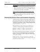
Testing Hardware with Scan Reporting
When a stylus interrupts an infrared beam, the software detects that
interruption and reports a touch. In scan reporting, the touch is defined
by physical beams that are interrupted in each axis. This type of
reporting is most useful for checking the functionality of the hardware,
since the report may identify beams that are not working.
Note
Scan reporting is not available for guided wave touch screens, nor is
it available for infrared touch screens using an SBC.
Using Scan Reporting
To start scan reporting, take the following steps:
1. From the Test Configuration Menu (Figure 3-1), press ENTER to
display the Test Menu.
2. From the Test Menu (Figure 4-1), select the Touch Coordinates
option.
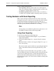
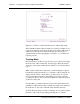
3. When the Touch Coordinates screen appears (Figure 5-1), type S to
enter scan reporting.
The screen contains a grid of small boxes, representing the physical
beams of the infrared touch system, along the left and top of the
screen.
In this example screen, the horizontal (x-axis) grid at the top of the
screen is numbered from 0 to 63 and the vertical (y-axis) grid at the left
of the screen is numbered from 0 to 47. Thus, this grid represents a
infrared touch frame with 64 physical beams along the x-axis and 48
physical beams along the y-axis, since beams are numbered starting with
0 rather than 1.