
User`s guide


Chapter 5 - Testing Touch System Hardware and Software CARROLL TOUCH
5-4 Touch System Diagnostics (CTDIAG) User’s Guide
corresponding beam is interrupted. If
Beam Trap Mode
is on, all grid
boxes should be highlighted at the end of the process. If a few grid boxes
remain not highlighted, run the stylus through those beams again to see
if they simply were not interrupted on the first pass.
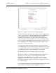
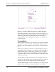
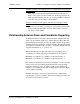
As an additional check, place the stylus in each corner of the screen; the
grid boxes for the maximum or minimum physical beam values should
highlight. In Figure 5-1, for example, those values are:
• Upper left corner 0, 0
• Upper right corner 63, 0
• Lower left corner 0, 47
• Lower right corner 63, 47
Troubleshooting
If an error message appears in the Message line, look up the suggested
actions in Appendix A, “Error Messages.” Other problems that may
arise during scan reporting, as well as their solutions, include:
Some beams read as interrupted.
• Check that all beams are clear of obstructions and that the bezel is
clean.
• Cycle the power to the touch system and try again. If the error
persists, contact Carroll Touch Technical Support.
There are gaps where you cannot cause beams to be interrupted.
• Enable the
Beam Trap Mode
of the Touch Coordinate Test screen,
and slowly move your finger along the x- and y-axes in order to
block every beam. If the corresponding grid boxes do not highlight,
contact Carroll Touch Technical Support.
All beams read as though they were being interrupted.
If you are using an HBC:
• Check that the controller card is installed properly.
• Check that the frame is connected to the controller.
• Check that the I/O address and interrupt number settings on the
controller match those shown on the Status line.
• Select another I/O address and interrupt number setting to avoid
possible conflict with other computer hardware. The addresses of
other hardware may be found in the IBM AT I/O Port Map in the
HBC installation instructions.