
User`s guide


Chapter 5 - Testing Touch System Hardware and Software CARROLL TOUCH
5-8 Touch System Diagnostics (CTDIAG) User’s Guide
If used in conjunction with
Exit Point Mode
, adding the modifier results
in double reporting of each exit point.
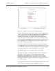
To add an Exit Point Modifier, type A.
Troubleshooting
If an error message appears in the Message line, look up the suggested
actions in Appendix A, “Error Messages.” Other problems that may
arise during coordinate reporting, as well as their solutions, include:
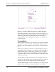
Touch Coordinates screen appears, but does not respond to touches.
If you are using an HBC or RS-232 controller, use scan reporting to
check the infrared touch screen.
If you are using an SBC or HBC:
• Check that the controller card is installed properly.
• Check that the touch frame is connected to the controller.
• Check that the I/O address and interrupt number settings on the
controller match those shown on the Status line.
• Select another I/O address and interrupt number setting to avoid
possible conflict with other hardware in the PC. The addresses of
other hardware may be found in the IBM AT I/O Port Map of the
SBC or HBC installation instructions.
If you are using an RS-232 controller or a Smart-Frame:
• Check that power is supplied to the RS-232 controller or
Smart-Frame.
• Check that the communication cable is properly connected to the
correct comm port.
• Ensure that the controller or Smart-Frame jumpers (if any) are set to
either autobaud or to a fixed baud rate and parity that matches those
shown on the Status line.
• Ensure that the stop bits parameter on the Status line is set to 1.
• Check that the port parameter on the Status line is set to the comm
port to which the touch system is connected.