
User's Manual


VisAccess AXS-100, AXS-100XT– Installation Guide
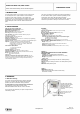
3.2 Metal Box Door Lock Assembly
The door lock assembly of the system metal box is presented in
figure 2 (the lock and the brass nut are supplied in the system
accessories box).
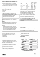
3.3 Backup Battery Installation (Optional)
Locate the optional backup battery (12V, 7.0Ah, Lead-acid
battery) in the lower left side of the system enclosure (see fig. 3).
3.4 Tamper Switch Installation & Wiring
It is necessary to protect the controller against tampering. A UL
Listed Tamper switch must be installed (see fig. 4) and wired to
AUXIN1 and COM of lock #3 of each controller.
2
1
Align lock with the pre-
pu n c h e d h o le a n d
insert it into the hole.
Place the brass nut on the
lock, tighten by hand and
finally tighten with
spanner (7/8”). Verify that
you can lock the door (key
rotation of 90 degrees).
Metal box
Metal box door
Backup
battery
(optional)
Figure 2 - Metal Cabinet Door Lock Assembly
Fig. 3 - Backup Battery Fig. 4 - Tamper Switch Installation
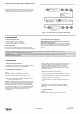
4. WIRING
AXS-100, AXS-100XT Wiring Diagram
F
2
Battery fuse 3.15A
LD3 (green LED)
ext. batt. charged
Replace fuses (x2) with UL
Listed fuses.
WARNING: To reduce risk of
fire, replace only with the same
type and rate of fuse.
NOTE:
Replace battery with PANASONIC.
Type: CR2032, 3V “COIN” battery.
Use of another battery may present
a risk of fire or explosion.
AC fuse 3.15A
LD2 (red LED)
Power ON
F
3
Plug-in transformer for AXS-100XT
only: PEI 120V/60Hz @ 0.59A,
S E C . 1 6 . 5 V A C / 5 0 VA .
B E 11 62 50 CA A 00 40 , B as l er
Electric. Class 2 NOT WET,
UL Listed 49HO.
Prox. Reader
BAT-
BAT+
READER 1
PWR
GND
TX
RX
RTE
GND
DPOS
RELAY 1
GND
PWR
NO
COM
NC
AC
AC
READER 2
PWR
GND
TX
RX
RTE
GND
DPOS
battery
-
+
holder
See user manuals for safety instructions.
Red
Black
Green
White
Symmetrical connectors
Door 1Door 2
LD4 (red LED) alarm
relay activated
LD5 (green
LED) output
relay activated
RTE input
RELAY 2
GND
PWR
NO
COM
NC
D.POS input
NOTE:
All power outputs are power limited
except from the battery outputs.
Note:
Optional for future use
DIP Switches
LD1 (green LED)
output relay
activated
DOOR 2
IN1
GND
IN2
DOOR 1
IN1
GND
IN2
EPROM
Wire Jumper
(remove for dry contact)
Twisted pair to A,B
of other AXS-100
Common gnd to
other AXS-100
must be connected!
Alarm relay
to Siren or
Bell
DB-9F
To computer
COM1 or COM2
1 2
6
3
7
4
8
5.
9
13 12 11 10
9
8
7
6
5
4
3
DB-25M
To serial printer
2
1
25 24 23 22 21 20 19 18 17 16 15 14
NOTE:
For battery
replacement
see
installation
instructions.
12V, 7.0Ah
Lead-acid battery
(optional)
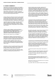
Lock connection configurations
Dry contact connectionInternal 12V power supply
GND
PWR
N.O.
COM
N.C.
Normally open (EMS)
Common
Normally closed (maglock)
GND
PWR
N.O.
COM
N.C.
Figure 5 - Wiring
www.elpas.com
Page 2 of 5
DE6280_V12_09/13