
User's Manual


VisAccess AXS-100, AXS-100XT – Installation Guide
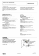
Each two-door controller connects to two proximity readers and two
electric locks. It can also be connected to two inputs per door:
Request-to-Exit (RTE) button or PIR near the door in the
secure area will allow a person to open the door from within for
leaving.
Door Position micro switch installed between the door and door
frame will provide the controller with door status indications.
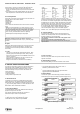
12VDC
Normally Open
NC
COM
NO
PWR
GND
----- Power
----- Power+Power+
Jumper
12VDC
Normally Closed
NC
COM
NO
PWR
GND
----- Power
Jumper
----- Power+
Non-12VDC or
high current
devices - Dry
contact N.O.
NC
COM
NO
PWR
GND
------
------
Non-12VDC or
high current
devices - Dry
contact N.C.
NC
COM
NO
PWR
GND
------
------
A. Proximity Readers
Each reader is connected to the controller via a 4-wire cable. The
standard cable is color coded as follows:
REDPower +
BLACK Power –
GREEN TX
WHITE RX
Use an extension cable with the same colors to avoid connection
errors.
Note: Do not install the RDR-4 on a metal surface or a metal
door frame, since this decreases the read range significantly. If
you have to install the reader on a metal surface, use a spacer
so that the reader will be at least 1 cm (3/8 in.) away from the
metal. You may use RDR-BACK which is an optionally
available spacer made specifically for this purpose
Note: When installing more than one RDR-4, the distance
between them should be at least 60 cm (2 ft.), to ensure proper
operation.
The lock sections include also 12V power connectors. These
connectors provide power to the lock with a current limit of 400mA
for each lock. The controller supplies power from a backup battery if
available when the AC power is down. Electromagnetic locks which
constantly draw a large current, should use the dry contact ONLY
without connecting the internal power supply. The same holds true
for any other device, which does NOT operate at 12VDC.
If you notice problems with a controller operating an EMS that
uses an internal power supply, connect the diode supplied
between + and – of the EMS output (see Panel Wiring Diagram).
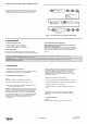
D. Controller Network
Up to eight system controllers can be connected together in a
network. The controller provides two 3-connector blocks for daisy
chaining controllers in a bus configuration.
The controllers’ addresses need not be in the physical order
of connection.
Connect system units with a single twisted pair cable.
Connect terminal A to A and B to B, GND to GND, this way up to
eight controllers.
B. Inputs
Both inputs (RTE and Door Position) can be connected to either
normally open or normally closed switches. The default is a
normally open RTE and normally closed Door Position (when
door is shut).
F. Power Connection
Connect the AC power cable to the power connector on the top
right side of the board.
G. Backup Battery Connection
Connect backup battery to black and red wires on the left side.
C. Locks
The system can operate both electromagnetic strikes - EMS
(normally open) and electromagnetic locks - EML (normally
closed). Each connector block has a COMMON as well as N.O.
and N.C. connectors.
If the controller is configured for one door, connect it to the
EMS/EML, at the left side of the controller.
All types of connections are detailed in the next drawing.
5. SPECIAL INSTALLER FUNCTIONS
The AXS-100 / AXS-100XT system has a few special functions,
which should not be accessible to the regular user. These
functions allow the installer to initialize the system to a known
state before starting to set up user data. The functions are:
Reset passwords
Clear key database
Load setup defaults
Setting address & operation mode
The controller will prompt you with a “Y/N”. Press “1”
followed by another Enter to confirm.
The keys database will be erased. The operation will be
logged and printed as “DB ERASED”.
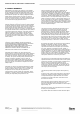
5.3 Setup Defaults
To return the system to its default setup, perform the actions that
are shown in figure 6 (text in rectangles represents displayed text).
Enter
5.1 Reset Passwords
If password #1 is not known, it is impossible to change some
system parameters. The following steps reset the passwords:
When the idle screen is displayed, repeatedly press the arrow up
( ) key until a long beep is heard. As a result, Password #1 has
been reset to “2975”. Password #2 is cleared.
ENTER PASSWORD
XXXX
DATE TYPE
Enter
SETUP
EDIT KEYS
EDIT REGISTER
LOCAL SETUP
SETUP FLAGS 1
------78
LOAD SETUP
DEFAULTS (Y/N)N
Enter DATE/TIME
5.2 Clear Keys Database
It is recommended to clear the key database before starting to
program user keys for the first time.
This operation should be performed from controller #1.
Follow these steps to clear the keys database:
Enter
APB RESET HOUR
99:00
PC PASSWORD
Enter 65535
(16 times)
Enter password #1 and log in into the system.
In EDIT KEYS menu select DELETE KEY screen.
Enter 9999 as the key number and press Enter.
1
LOAD SETUP
DEFAULTS (Y/N)Y
Enter (long beep is heard
to indicate success)
Figure 6 - Returning to Setup Defaults
www.elpas.com
Page 3 of 5
DE6280_V12_09/13