
User's Manual


Low Frequency Exciters - Installation Guide _________________________________________________________________________________________
Page 2 of 8
DTA03N01_V13
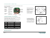
The key setup and configuration circuitry components used by the standalone or master
RF Exciter are detailed below
Unit ID Number
DIP Switches
Used for manually setting the
unit ID number of a master
or standalone LF Exciter.
Output Power
Control
Potentiometer
Used for manually tuning the
size of generated output
detection field
Power Source
Interface
Female RJ11 connector to
external 24 VDC nominal
power source via the EJB
junction box
LF Master/Slave
Interface
Female RJ45 connector to
LF Exciter slave unit
(master/slave configuration)
Setting the ID Number of the LF Exciter
Each Stand-alone or Master LF Exciter must be assigned a unique ID number
to make it possible for EIRIS to recognize the device. Locate the DIP switches
on the circuit board of the exciter and set the switch
settings as required. Use a scientific calculator or in EIRIS, the General tab of
the reader configuration for to determination the correct switch settings.
Refer to the table below for unit numbers to avoid using:
NO INVALID LF EXCITER ID (HEX) INVALID LF EXCITER ID (BIN)
1 13 00010011
2 35 00110101
3 4B 01001011
4 4D 01001101
5 5C 01011100
6 B8 10111000
7 D5 11010101
8 DC 11011100
CAUTION: Set the DIP switch before powering up the LF Exciter.
Never change the DIP switch settings once the LF Exciter is powered up.
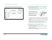
Wiring the LF Exciter
Power from an external source
(24 VDC nominal ± 30%; 200mA)
is supplied to a standalone or
master LF Exciter via the EJB
junction box.
A bus topology network may be
branched for LF Exciters by
connecting only the power
connectors as shown here.
For connecting a standalone or
master LF Exciter to a EJB junction
box, use an unshielded 6 conductor
26 AWG solid cable crimped at both
ends with a RJ11 (6P6C) connector.
Ensure that the correct order of the
wires is maintained as shown here.
1 +V
2 - V
3 DATA
4 DATA
5 -V
6 +V