User Manual 905U-G Wireless Gateway ELPRO Technologies Pty Ltd, 9/12 Billabong Street, Stafford Q 4053, Australia. Tel: +61 7 33524533 Fax: +61 7 33524577 Email: sales@elprotech.com Web: www.elprotech.
Important Notices Thank you for your selection of the 905G module. We trust it will give you many years of valuable service. ATTENTION! Incorrect termination of supply wires may cause internal damage and will void warranty. To ensure your 905G enjoys a long life, double check ALL your connections with the user’s manual before turning the power on. Caution! For continued protection against risk of fire, replace the module fuse F1 only with the same type and rating.
905U-G Wireless Gateway User Manual FCC Notice: This user’s manual is for the ELPRO 905U-G radio telemetry module. This device complies with Part 15.247 of the FCC Rules. Operation is subject to the following two conditions: 1) This device may not cause harmful interference and 2) This device must accept any interference received, including interference that may cause undesired operation. This device must be operated as supplied by ELPRO Technologies Pty Ltd.
Important Notices Important Notice ELPRO products are designed to be used in industrial environments, by experienced industrial engineering personnel with adequate knowledge of safety design considerations. ELPRO radio products are used on unprotected license-free radio bands with radio noise and interference. The products are designed to operate in the presence of noise and interference, however in an extreme case, radio noise and interference could cause product operation delays or operation failure.
905U-G Wireless Gateway User Manual Limited Warranty, Disclaimer and Limitation of Remedies ELPRO products are warranted to be free from manufacturing defects for a period of 2 years from the effective date of purchase. The effective date of purchase is decided solely by ELPRO Technologies.
Contents CONTENTS CHAPTER 1 INTRODUCTION 1.1 905G OVERVIEW 1.1.1 Modbus / DF1 905G 1.1.2 Profibus 905G 1.1.3 Ethernet 905G 1.1.4 DeviceNet 905G 1.1.5 Modbus Plus 905G 1.2 THE 905G STRUCTURE 1.2.1 On-board I/O 1.2.2 I/O Expansion - 105S modules 1.3 THE WIRELESS NETWORK 1.3.1 905U to 905G Network 1.3.2 905G to 905G Network 1.3.3 “Data Concentrator” Networks 1.3.4 905G Repeaters CHAPTER 2 OPERATION 2.1 START-UP 2.2 OPERATION 2.3 DATABASE 2.4 THE HOST - 905G LINK 2.4.1 Modbus / DF1 2.4.2 Profibus 2.4.
905U-G Wireless Gateway 4.2.2 Security 4.3 MAPPINGS 905G TO 905U I/O MODULES 4.3.1 Mappings from Inputs at Remote 905U I/O Modules 4.3.2 Mappings from 905G to Outputs at Remote 905U I/O Modules 4.3.3 Don’t Send if in Comm Fail 4.3.4 Startup Polls 4.3.5 Polls to Remote Modules 4.4 MAPPINGS FROM 905G TO OTHER 905G MODULES 4.4.1 Entering a Block Mapping 4.4.2 Host Device Trigger 4.4.3 Time Period 4.4.4 Real-Time Change-of-State 4.4.6 Mixing Normal Mappings and Block Mappings 4.4.
Contents 6.4 FIELDBUS INDICATING LEDS 143 CHAPTER 7 WARRANTY 149 APPENDIX 1 STATUS REGISTERS 151 APPENDIX 2 IT FUNCTIONALITY 153 MAN_905G_1.
05U-G Wireless Gateway User Manual Chapter 1 INTRODUCTION 1.1 905G Overview The 905U-G Wireless Gateway products provide a wireless interface between various fieldbus protocols used in process and automation 905U I/O applications. The 905U-G includes an integral 900MHz license-free radio transceiver, and transfers transducer and control signals (I/O) using Direct I/O Profibus a highly secure and highly reliable radio protocol.
Chapter One Introduction The 905U-G is referred to as the 905G for the rest of this document, to clearly differentiate from normal 905U I/O modules. Ordering information: 905U-G-MD1 Modbus Master & Slave / DF1 interface 905U-G-PR1 Profibus-DP Slave interface 905U-G-PR2 Profibus-DP Master interface 905U-G-ET1 Ethernet interface - Modbus TCP, Ethernet IP, FTP, HTML, Email 905U-G-DE1 DeviceNet Slave interface 905U-G-M+1 Modbus Plus Slave interface 1.1.
905U-G Wireless Gateway User Manual The Profibus 905G I/O database has 4300 registers (each of 16 bit value), however the Profibus interface limits the amount of I/O that can be transferred via the Profibus port. Slave unit (PR1). The PR1 slave unit only supports 416 x 8 bit bytes of I/O. Of the 416 bytes of I/O, there is a maximum 244 input bytes and maximum 244 output bytes - that is, if 244 input bytes are used then only 172 output bytes can be used (416 – 244).
Chapter One Introduction byte can be 8 discrete inputs or outputs, but analog or pulse I/O take up 1 byte for low resolution values (8-bit) or 2 bytes for high resolution values (16-bit). An “output” is a value coming into the 905G via the fieldbus. An input is a value going out from the 905G via the fieldbus. So an Ethernet 905G can handle up to 4300 I/O total, but analog or pulse inputs are limited to 2048 x 8-bit values or 1024 x 16-bit values. The same limit applies to outputs.
905U-G Wireless Gateway User Manual 1.2 The 905G Structure The 905G has three functional sections: • The Radio Interface consists of an I/O database (or "Process Image") that maintains the latest values of all I/O in the wireless I/O system. The I/O database comprises 4300 x 16 bit I/O registers and 4300 x 16 bit status registers. There are also other registers in the database that can be used for system management - they are discussed later in this manual.
Chapter One Introduction 1.2.1 On-board I/O The 905G has eight on-board discrete I/O. Each I/O point can be used as either a discrete input (voltage free contact input) or discrete output (transistor output) - an I/O point cannot be used as both input and output. Each I/O point is linked to two separate I/O registers in the database - one for the “input” function and one for the “output” function..
905U-G Wireless Gateway User Manual 905U modules can transmit input messages directly to outputs on other 905U module, as well as the 905G. The same input can be transmitted to different addresses by entering two "mapping" configurations at the remote module. 905U-3 905U-K 905U-G Normal 905U Messages I/O registers in a 905G can be configured (mapped) to outputs at remote 905U 105S-2 905U-1 modules, or I/O registers in 905G modules.
Chapter One Introduction As well as the normal “I/O change” messages and update messages, the 905G has “block read” and “block write” messages for use with other 905G modules. These messages will transmit multiple register values instead of only one as in the normal 905U message. The block read/write messages increase the efficiency of radio communications where a 905G “sees” a large number of changes in its database at the one time.
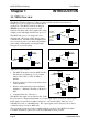
905U-G Wireless Gateway User Manual NETWORK OF 905U I/O UNITS TO HOST DEVICE 905U-G 905U-G NETWORK OF 905U I/O UNITS 905U-G This type of network reduces the amount of radio traffic and is suitable for systems with a large number of I/O modules. The system is divided into local sub-networks, each with a 905G unit. The 905U modules transmit their I/O vlaues to the 905G.
905U-G Wireless Gateway Chapter 2 User Manual OPERATION 2.1 Start-up The 905G operating software and the database configuration are stored in non-volatile memory, however the database I/O register values are lost on power failure (in the same way as a PLC). On start-up, the 905G sends "start-up poll" messages to remote modules based on the source address of inputs configured in the database (the start-up messages can be disabled by configuration).
Chapter Two Operation binary/digital read command, the 905G will convert the 16 bit value into a binary (1 bit) value before it responds. #14 #1 DIN1 905U-1 905U-G An example of normal operation - assume that a remote module has address 14 and the 905G is address 1. Module #14 is configured with a mapping DI1 → I/O Reg 76 at #1. When DI1 turns "on", module #14 transmits a message.
905U-G Wireless Gateway User Manual 2.3 Database The 905G database (Radio Interface) has 10 000 registers, each of 16 bit size.
Chapter Two Operation voltage is also monitored, and an alarm is available at register 4309. This becomes active if the supply voltage falls below 8.0V, and clears when the supply voltage rises above 9.0V.
905U-G Wireless Gateway User Manual 2.4.2 Profibus The Profibus port has auto-detect of baud rate from 9600 bits/sec to 12Mbit/sec - no configuration is required. The Profibus units have internal hardware comprising the Profibus Interface. The Profibus Interface handles all Profibus DP Network communications. The internal Radio Interface is separate to the Profibus Interface, and handles all radio communications.
Chapter Two Operation Each 905U module can have up to 31 x 105S modules connected to it. These modules are addressed 96 - 127. More than one 105S module can have the same address, provided they are not connected to the same 905U module - that is, #100 via #16 is identified as a different module to #100 via #65. A constraint that needs to be considered is the capacity of the radio channel. If there is too much traffic on the radio channel, then the system quickly becomes unreliable.
905U-G Wireless Gateway User Manual For I/O registers which are mapped to a remote output or another 905G, the comms fail status is set if the 905G does not receive an acknowledgment for a message being sent to that remote output. The comms fail status resets when a successful transmission occurs. For I/O registers which have been mapped , from a remote input or another 905G, a comms fail time period may be configured.
Chapter Two Operation comms problem (this means that the corresponding update time for the input at the 905U will need to be short). If the point is an output, then the update time for the output should be made short. 2.7 Security Considerations There are three dimensions of security considerations: 1. Failure to operate when required - or “operational reliability”. The features discussed above optimize operating reliability.
905U-G Wireless Gateway Chapter 3 User Manual INSTALLATION 3.1 General The 905G module is housed in a rugged aluminum case, suitable for DIN-rail mounting. Terminals will accept wires up to 12 gauge (2.5 sqmm) in size. All connections to the module must be low voltage (SELV). Normal 110-240V mains supply should not be connected to any terminal of the 905G module. Refer to Section 3.3 Power Supply. Before installing a new system, it is preferable to bench test the complete system.
Chapter Three Installation antennas inside buildings. An obstructed path requires testing to determine if the path will be reliable - refer the section 6 of this manual. Where it is not possible to achieve reliable communications between two modules, then another 905U or 905G module may be used to receive the message and re-transmit it. This module is referred to as a repeater.
905U-G Wireless Gateway User Manual Where antennas are mounted on elevated masts, the masts should be effectively earthed to avoid lightning surges. For high lightning risk areas, surge suppression devices between the module and the antenna are recommended. If the antenna is not already shielded from lightning strike by an adjacent earthed structure, a lightning rod should be installed above the antenna to provide shielding. 3.2.1 Dipole and Collinear antennas.
Chapter Three The Yagi gain also acts on the receiver, so adding Yagi antennas at both ends of a link provides a double improvement. Installation 90o Yagi antennas are directional. That is, they have positive gain Antenna installed to the front of the antenna, but with drain holes down negative gain in other directions.
905U-G Wireless Gateway User Manual 3.3.1 AC Supply The AC supply is connected to the “SUP1” and “SUP2” terminals as shown below. The AC supply should be “floating” relative to earth. 12 – 24 VAC Power Supply AC Out SUP1 SUP2 GND BAT+ Optional Battery Fuse 5A - 105U-G + 3.3.2 DC Supply For DC supplies, the positive lead is connected to “SUP1” and the negative to “GND”. The positive side of the supply must not be connected to earth. The DC supply may be a floating supply or negatively grounded.
Chapter Three Installation On return of normal supply, the unit will recharge the battery. The maximum output of the battery charger is 0.7A when the supply voltage is greater than 12V, and 0.3A for less than 12V. The 105G monitors the power supply and provides the following internal values, which can be mapped as I/O values: • Power failure (I/O Reg 4309) - if the supply voltage drops below 8V, this status value is set on, and set off again when the voltage is more than 9V.
905U-G Wireless Gateway User Manual All eight of the 105G DIO terminals may also be used as discrete outputs. The digital outputs are transistor switched DC signals, FET output to common rated at 30VDC 500 mA. Digital outputs may be configured to individually turn off if no command message is received to that output for a certain period. This feature provides an intelligent watch dog for each output, so that a communications failure at a transmitting site causes the output to revert to a known state.
Chapter Three Installation Hardware handshaking using the CTS/RTS lines is provided, and are under the control of the Host Comms Driver. Example cable drawings for connection to a DTE host (a PC) or another DCE host are detailed below: 905U-G DB9 905U-G DB9 3.5.2 RS485 Serial Port RS485 should not be used with the DF1 unit. The RS485 port provides for communication between the 905G unit and its host device using a multi-drop cable. Up to 32 devices may be connected in each multi-drop network.
905U-G Wireless Gateway User Manual It is important to maintain the polarity of the two RS485 wires. On the 905G, terminal A (the terminal on the right) is positive and terminal B is negative.
Chapter Three Installation 3.6 Profibus Port The Profibus RS485 connector is a D9 connector in the top end-plate of the module (see below). 905U-G-PR1 (Profibus Slave) End Plate: PROFIBUS D9 CONNECTOR RS485 TERMINATION SWITCH SELECTOR SWITCHES DIAGNOSTIC LED’s CONFIGURATION ENABLE ANTENNA CONNECTION Note: If the “Use Rotary Switch Address” option in configuration software is selected, the two rotary switches are used to specify the Profibus Node Address in the range 0 – 99.
905U-G Wireless Gateway User Manual Pin Description 1 Not connected 2 Not connected 3 +ve RS485 (Positive) 4 RTS (request to send) 5 GND - Isolated GND from RS485 side 6 +5V - Isolated 5V from RS485 side 7 Not connected 8 -ve RS485 (Negative) 9 Not connected 3.7 Ethernet Port For 905U-G-ET1 modules only. The Ethernet connection uses a standard RJ45 connector on the top end-plate of the module. The selector switches should all be “off” (in the diagram below, “off” is up).
Chapter Three Installation 3.8 Modbus Plus Port For 905U-G-M+1 modules only. Connection to the Modbus Plus Network is via the 9-pin D-SUB connector located at the antenna end of the module. Pin-outs are outlined in the table below. D9 MODBUS PLUS CONNECTION SELECTOR SWITCHES DIAGNOSTIC LED’s CONFIGURATION ENABLE ANTENNA CONNECTION See section on configuration for description of selector switches.
905U-G Wireless Gateway User Manual 3.9 DeviceNet Port For 905U-G-DE1 modules only. Connection to the DeviceNet Network is via the 5-pin plugable screw terminal connector located at the antenna end of the module. Pin-outs are specified below.
905U-G Wireless Gateway Chapter 4 User Manual CONFIGURATION 4.1 Introduction A Windows program is provided to configure the 905U system. The configuration is done on a system basis - referred to as a “project” in the program. After the system configuration is entered, the configuration file can be loaded into each module via the RS232 port.
Chapter 4 Configuration 4.2 Configuration Program The configuration software is available on a CD, and needs to be installed on your PC before you can use it. The CD contains a setup file called setup.exe. Select the configuration software window on the Product CD and an installation Wizard will guide you through the installation procedure. To upload and download configuration files to a module, you will need a RS-232 serial cable as shown below.
905U-G Wireless Gateway User Manual screen will appear where you may enter the system address. If you are editing an existing project, the system address will already have been entered. Do not change the system address unless you are going to reprogram all of the modules in the system. Password. You have the option of entering a password to protect the configuration files against unauthorized changes.
Chapter 4 Configuration Loading configuration from an existing module To load the configuration from a module, connect the module to the PC via the RS232 cable, put the module into “Configuration Mode” by pressing the configuration button on the top end-plate, and click on “Load Unit”. This will allow you to view the module configuration, change it, or copy it for another module - refer to section 4.10 for full details.
905U-G Wireless Gateway User Manual Deleting a Unit A module can be deleted from the configuration by highlighting the unit and selecting “Delete Unit”.
Chapter 4 Configuration 4.2.2 Security There are two security features available. You can enter a password to protect the configuration files, and you can enable security encryption of the radio transmissions. The password can be between 6 and 256 characters. The password is case sensitive and any ASCII characters can be used. If you have entered a password, then this password will need to be entered whenever the configuration is changed. You are able to change the password from the “Utilities” menu.
905U-G Wireless Gateway User Manual The archived configuration files cannot be changed, downloaded or uploaded without the password. Warning!! These security options provide a high level of security, but no data-security system can provide “100% protection”. But it does make it very difficult for someone to interfere with the 905U system - difficult to the point where there would be many easier alternate ways to cause malicious damage. The password must be kept in a secure place.
Chapter 4 Configuration 4.3 Mappings 905G to 905U I/O Modules To transfer remote input signals to a 905G, or transfer a value to a remote output from a 905G, you set up “I/O mappings”. You enter mappings into the source unit, not the destination unit. That is, you configure a mapping at the “input” module. If you want to transfer an input signal at a 905U module to a 905G register, you enter a mapping at the 905U I/O module.
905U-G Wireless Gateway User Manual Any I/O registers that have already been selected will have a color shading. The update times, analog sensitivities for these mappings can be set as per normal I/O mappings. To map several inputs to consecutive I/O registers, use “Shift”-select or “Ctrl” - select to highlight the inputs, and select the first I/O register in the range. The selected mappings will be entered with consecutive I/O registers.
Chapter 4 Configuration To set the comms fail times, select the 905G, and select the “Comms Fail Time” option. Each remote input already mapped to the 905G will automatically be listed, including the remote module containing the mapping. The default value for the comms-fail time is “disabled” or zero. To enter a time, select the I/O register from the list. The comms-fail time should be greater than the update time of the remote input. 4.3.
905U-G Wireless Gateway User Manual You can configure the amount of change required to trigger a change message - this is called the change sensitivity. Sensitivities are configured for blocks of I/O registers - that is, each I/O register does not have a unique sensitivity. You can configure up to 50 sensitivity values - that is, there can be 50 blocks of registers with different sensitivities. For more information on this, refer to section 4.5.
Chapter 4 Configuration Update Times To change the update times of output mappings, select the Update Times option. Any I/O registers that have already been mapped to remote outputs will automatically be listed. The default update time is 10 minutes. Changing Multiple Settings You can change the Comms Fail Times or Update Times of several I/O points simultaneously by using the Select feature.
905U-G Wireless Gateway User Manual To configure this special mapping, select the “New Don’t Send in Comms Fail Mapping” box. You will be asked to select which remote module this function applies to. You can enter more than one of these mappings if there are more than one modules. 4.3.4 Startup Polls You can enter start up polls for remote modules by using the “New Poll Mapping” box. This function is the same as for the 905U I/O modules. A start-up poll is a special message sent when the 905G starts up.
Chapter 4 Configuration Read/Write Mappings The mappings can be “read” or “write” mappings. A Read mapping is a request sent to another 905G to return a block of values. A Write mapping is a message sending a block of values to another 905G. A Read mapping from 905G#2 to 905G#3 could be the same as a Write mapping from 905G#3 to 905G#2 (that is, in the reverse direction) - except the Read mapping is initiated from #2 and the Write mapping is initiated from #3.
905U-G Wireless Gateway 4.4.1 User Manual Entering a Block Mapping Select the “source” 905G on the left hand menu - select “Block Mappings” and then “New Block Mapping” from the right-hand display. The Block Mapping Configuration display will appear. Select the “Command Type” from the pop-down window in the centre of the display. The red arrow will confirm the direction of the block transfer. Now select the destination module - only the 905G modules already configured will be shown.
Chapter 4 Configuration In the above example, the status register for the block mapping has been automatically assigned to register 9500. The rest of the mapping configuration involves the mapping trigger - or what initiates the mapping message. Mapping “Triggers” A block mapping can be “triggered” or initiated by several different methods. • By the host device writing to a “trigger register” in the source 905G - the block mapping message is sent each time the host device writes to the trigger register.
905U-G Wireless Gateway User Manual 4.4.3 Time Period On the Block Mapping display, there are two configuration windows - “Period” and “Offset” - these determine the time period trigger and real-time trigger. For a time-period trigger, select “Continuous” in the “Period” pop-down window. Under “Offset” enter the time-period in seconds. In the above example, the mapping will be sent every 300 seconds or 5 minutes.
Chapter 4 Configuration 4.4.4 Real-Time The block mapping message can be sent at a real-time by setting the “Period” value. In this example, “period” is set to 6 minutes - the message will be sent every 6 minutes starting at the beginning of each hour. That is, the message will be sent at XX:00, XX:06, XX:12, XX:18, XX:24 …. XX:54 - where XX represents any hour of the day. If “Period” was set to 1 minute, then the message would be sent every minute, on the minute.
905U-G Wireless Gateway User Manual 4333. On power-up, these registers are set to zero. Reg 4333 increments each second, Reg 4332 increments each minute, Reg 4331 each hour and Reg 4330 each day. The clock registers are used by the 905G for the real-time-clock trigger. The host device can read these registers. The host device can also set the 905G clock at any time by writing to the appropriate Set register. The Set registers are : 4340 – 4343.
Chapter 4 4.4.5 Configuration Change-of-State If a value in the block changes by more than the sensitivity amount, then the block message will be sent (this can only occur for Write mappings). The sensitivity values are set under the “Sensitivity” option as per section 4.5. A delay time can be entered to reduce the number of change triggers in active systems.
905U-G Wireless Gateway User Manual 4.4.8 “Repeater-only” Configuration Any 905G module can act as a repeater unit. However a 905G may need to be installed as a repeater only (that is, there is no host device connected). In this case, the base 905G, the 905UG-MD1 unit would normally be used as this is the lowest cost of the 105G modules. A repeater can be configured as a “Repeater-only” unit.
Chapter 4 Configuration trigger will occur for register 34. Sensitivity values are in decimal and can vary between 1 and 65535 (16-bit). Up to 50 blocks of sensitivities can be configured. If a register is included in more than one block, then the first sensitivity value configured will be accepted and later values ignored. Registers which are not included in any block use the “default” sensitivity which is also userconfigurable.
905U-G Wireless Gateway User Manual 4.6 Serial Configuration - MODBUS The 905U-G-MD1 module provides interface for Modbus Slave, Modbus Master and AllenBradley DF1. This Modbus interface uses the Modbus RTU protocol - also known as the Modbus Binary protocol. This manual assumes that the reader has a good understanding of the Modbus or DF1 protocol. 4.6.1 MODBUS Slave If you use the 905G Modbus Slave interface, then the host device will be a Modbus Master device.
Chapter 4 Configuration Supported Modbus Function Codes: Function Meaning Code 01 Read the state of multiple digital output points 02 Read the state of multiple digital input points 03 Read the value of multiple output registers 04 Read the value of multiple input registers 05 Set a single digital output ON or OFF 06 Set the value of a single output register 07 Read Exception Status - compatibility - returns zero Loopback test Supported codes 0 return query data 10 clear diagnostic counters 1
905U-G Wireless Gateway User Manual Supported Exception Codes: Exceptio n Code Name Description 01 Illegal function The module does not support the function code in the query 02 Illegal data address The data address received in the query is outside the initialized memory area 03 Illegal data value The data in the request is illegal 06 Busy Unable to process message 4.6.2 MODBUS Master If you use the 905G as a Modbus Master, then the host device/s will be Modbus Slave device/s.
Chapter 4 Configuration command is a “Digital” write, meaning that the register values will be written as digital/binary values”. If the Modbus Slave device does not respond to the Modbus command, the 905G will try another 3 times (“Max Retries” = 3). The Modbus command will be sent to the Modbus Slave every 100msec. The address of the Modbus Slave is 1 (permissible addresses are 1 – 255).
905U-G Wireless Gateway User Manual To complete the Fieldbus Configuration, enter any other Modbus commands that may be required to transfer I/O points between the 905G and the Modbus Slave devices. Digital I/O The value of a digital I/O point is stored in the 905G database as a hexadecimal '0000' (“off”) or hex 'FFFF' (“on”). However the 905G will generate either a ‘0’ (“off”) or ‘1’ (“on”) to a digital output point (Coil) when sending commands to a Modbus slave - these are commands 05 and 15.
Chapter 4 Configuration When updated values are received from the 905U radio network, the current polling sequence is interrupted, and the new values are written immediately to the appropriate slaves. Re-tries on the Serial Port When communicating with Modbus slaves, the 905G may be configured to re-try (or re-send) a message zero or more times if no response is received from a slave. If all retries are used up, that slave is flagged as being in communication failure.
905U-G Wireless Gateway Command Description User Manual Code Function Code Comment Protected Write 0x00 NONE PLC2 series and SLC / Micrologix Unprotected Read 0x01 NONE PLC2 series and SLC / Micrologix Diagnostic Status 0x06 Diagnostic Commands Echo message Unprotected Write 0x06 0x08 0x00 0x00 NONE PLC2 series and SLC500 / Micrologix Typed logical Read Read Bits 0x0F 0x0F 0xA2 0xA2 Read Integers 0x0F 0xA2 Type SLC500 and Micrologix 0x85 Reads MSB of each 905G I/O register and wri
Chapter 4 Configuration If the 905G acts as a command initiator, you can enter a “Request Delay” between commands sent to the host. To enter a DF1 command, select “New Serial Mapping”. The following example is a file write command which writes 905G I/O registers 80 – 104 (25 registers) to DF1 files I3.1 to I27.1 at DF1 address 2. The entry under “I/O Register” (see below) is the first I/O register in the 905G to be transferred - the “I/O count” is the number of registers to be transferred.
905U-G Wireless Gateway User Manual Discrete I/O The value of a digital I/O point is stored in the 905G database as a hexadecimal '0000' (“off”) or hex 'FFFF' (“on”). However the 905G will generate either a ‘0’ (“off”) or ‘1’ (“on”) to a binary file when initiating a “Typed Logical Write” command or responding to a “Typed Logical Read” command.
Chapter 4 Configuration then mask out the high 16 bits (MVM with mask value FFFF). This will result in a long integer value in the range 0 to 65535. Alternatively, use a long integer file type to transfer the analog value as a long integer in the range 0-65535. Pulse I/O Pulse counts from the remote 905U modules are shown as a 16-bit register. When the register rolls over, from ‘FFFF’ (hex), the next value will be ‘0001’.
905U-G Wireless Gateway User Manual 4.8 Fieldbus Configuration All 905G modules (except MD1) have separate internal hardware comprising the Fieldbus Interface, consisting of a separate microprocessor and appropriate hardware for the network connection. This Fieldbus Interface handles all fieldbus communications, and transfers I/O in the Fieldbus Interface Registers to/from the fieldbus.
Chapter 4 Configuration Radio Interface Fieldbus Interface IN Area Profibus 244 Bytes Modbus/TCP 2048 Bytes Write from I/O Reg Ethernet/IP allows 6 input connections; each connection Max 512 bytes Read from Host Modbus Plus 2048 bytes DeviceNet 512 bytes 10,000 x 16-bit I/O Registers OUT Area Profibus 244 Bytes Modbus/TCP 2048 Bytes Read to I/O Reg Ethernet/IP allows 6 output connections; each connection Max 512 bytes Write from Host Modbus Plus 2048 bytes DeviceNet 512 bytes 905G Module 4.8.
905U-G Wireless Gateway User Manual Fieldbus Mapping Types Transfer Mode Read Mapping Write Mapping Single Bit The 905G reads a block of consecutive bits from Fieldbus OUT Area and stores each bit in consecutive I/O Registers, as hex FFFF or 0000. The 905G takes the MSB (most significant bit) of a block of consecutive I/O Registers, converting the 16 bit I/O register values into 0 or 1, and writes to consecutive bits of Fieldbus IN Area.
Chapter 4 Configuration The Fieldbus Interface IN and OUT areas are simply a block of I/O memory, exchanged according to the configured protocol. For example, with a Profibus slave that supports 244 bytes of inputs, the fieldbus interface IN area could be addressed either as byte locations 1 to 244 or as word locations 1 to 122.
905U-G Wireless Gateway User Manual Three Fieldbus Mappings are illustrated in the example above. Note that “Word Address Mode” is selected, meaning that the Fieldbus Interface IN and OUT Areas will be treated as word-addressed arrays by configuration software. The parameters for each fieldbus mapping were setup using the mapping configuration screen as described above.
Chapter 4 Configuration The first Fieldbus Mapping is a “Write WORD” mapping, writing I/O Registers 10 – 15 from the Radio Interface to word-locations 1 – 5 in the Fieldbus IN Area. Because the transfer mode is “word” complete 16-bit registers are transferred. The second mapping is a “Read BIT” mapping, reading 12 bits from Fieldbus OUT Area word-location 1(word address mode is selected) to I/O Registers 30 – 41.
905U-G Wireless Gateway User Manual example). The dark blue area in the register selection screen above shows the extent and location of the current fieldbus mapping graphically. The status panel at the bottom of the window always displays the extent of the current selection, which can be seen to be word 1, bit 12 to word 2, bit 3. A status location (4500) may be used to give the host device status information about the Fieldbus Interface.
Chapter 4 Configuration 4.10 Fieldbus Configuration - Profibus Master The 905U-G-PR2 implements a complete Profibus-DPV0/DPV1 master. The hardware is optimized for high throughput and can be used in mono or multi master networks up to 12 Mbit/s. Up to 125 slaves with a total max of 2048 byte input and 2048 byte output data can be connected. 4.10.1 GSD File Each device in a Profibus network is associated with a GSD file, containing all necessary information about the device.
905U-G Wireless Gateway User Manual 4.10.3 Configuration Profibus network configuration is performed via the ESeries Configuration Utility. The 905G Profibus Master provides up to 2048 bytes of inputs and 2048 bytes of outputs in the fieldbus interface for I/O on the profibus network. I/O in the fieldbus interface must be linked with I/O in the radio interface via appropriate fieldbus mappings (see 4.8 Fieldbus Configuration above) for I/O transfer with the radio network.
Chapter 4 Configuration selected in the busview so that the network list is displayed in the listview rather than the slave I/O configuration list). The above example shows a slave device being added to the network at node address 7. Slave Address To change the node address of a slave already configured on the network, locate the slave in the network listview and drag it to the position in the list corresponding to the desired address.
905U-G Wireless Gateway User Manual Group Assignment If the slave supports sync/freeze functionality, it can be assigned to the masters sync/freeze groups by clicking on the checkboxes. The sync/freeze assignment of the groups is also displayed (these can be changed via the master properties dialog). Parameter Assignment A slaves user-specific parameters can be changed via the parameter assignment page.
Chapter 4 Configuration be edited directly (consult the device specific documentation for the meaning of these values). Adding I/O to a Slave The possible I/O combinations for a given slave may be fixed or configurable (i.e. modular) depending on the GSD file for the device. When the I/O configuration is fixed, the fixed I/O are always defined whenever the device is added to the network. However, for modular devices, the I/O configuration must be assigned manually.
905U-G Wireless Gateway User Manual I/O modules may also have associated user parameter data defined by the corresponding GSD file. The meaning of these parameters (if applicable) is specific to the slave implementation, and may be altered via the Parameter Assignment tab of the Module Properties form. Configuration software also provides an additional I/O module to all slaves that is not defined in the GSD files, which is the Universal Module.
Chapter 4 Configuration parameters (see Bus Parameters Tab below). The storage format determines if word values are stored in big endian (Motorola – most significant byte has lowest address) or little endian (Intel – Least significant byte has lowest address) format. Group Properties Tab A DP master can send the SYNC and/or FREEZE control commands simultaneously to a group of slaves for synchronization purposes. Therefore the slaves must be assigned to Sync/Freeze - groups.
905U-G Wireless Gateway User Manual Tqui The quiet time is the time a modulator needs after recognizing a send frame to switch from send to receive. 0 t_bit <= Tqui <= MIN(31 t_bit, Min. Tsdr - 1) Gap Factor The Gap Factor determines how many token rounds occur before a new active node (master) can be added to the token ring. 1 <= Gap Factor <= 100 Retry Limit The Retry Limits determines the number of attemps (repeated message frames) allowed to access a node.
Chapter 4 Configuration 256 t_bit <= Ttr <= 16.776.960 t_bit Non-adjustable bus parameters Ttr The target rotation time determines the maximum available time for a token pass. During this time all active nodes (masters) obtain the token one time to send data. ESeries Config Software calculates an optimized Ttr depending on the values of other bus parameters. If an individual bus parameter is changed, pressing the Recalculate-button recalculates the Ttr including Delta_Ttr.
905U-G Wireless Gateway User Manual Configuration Example: The Following example describes a simple configuration of a 905G connected to a simple Profibus Slave I/O device. Described is the configuration of the local 905G Profibus master only, for more detailed configuration examples, an application note can be downloaded from www.elprotech.com. The example will transfer 8 x digital points from the radio network to the slave device.
Chapter 4 Configuration 2) Fieldbus Configuration. The next configuration step is to transfer the I/O in the Fieldbus Interace to the Radio Interface so that the profibus I/O is available to the radio network. The 8 x digital output to be sent to the profibus slave are transferred using a fieldbus write mapping. Since the 8 x digital outputs are all contained in a ‘1 Byte Out’ module, we use ‘Single Bit Mode’ for the fieldbus write mapping.
905U-G Wireless Gateway User Manual 3) Radio Configuration To complete the configuration, the I/O that has now been transferred to the radio interface must be mapped over the radio network. The analog input from the slave is mapped to an analog output at a remote 905U-1, the 8 x digital output at the profibus slave will be activated in this example via appropriate mapping from 8 x digital input at a remote 905U-4 (see below).
Chapter 4 Configuration 4.10.4 Message Interface In addition to cyclic data exchange with slave devices, the 905G Profibus Master also supports a number of acyclcic services that may be triggered via a special Message Interface. The message interface is by default disabled, but will become enabled by also enabling a “Status Location” via the fieldbus configuration tab in configuration software.
905U-G Wireless Gateway User Manual The message interface supports the following types of communication: • Command - Response A message is sent by the message initiator, and the message recipient is required to respond. The message initiator can be either the 905G or host device. • Indication A message is sent by the message initiator, and no response is required. The message initiator can be either the 905G or host device.
Chapter 4 Configuration Message Information This register contains information about whether the message is a command or a response, and may also indicate an error (see below). b15 b14 b13 b12 b11 b10 Err C/ R (reserved) b9 b8 b7 Error Code b6 b5 b4 b3 b2 b1 b0 Message Type For example, a command message will always contain the value 4002h in this register. A response message will contain 0002h, and may contain error information as detailed in the table below.
905U-G Wireless Gateway User Manual Extended Words 1 ... 8 These registers are specific for each command. Consult the specification for each command for further information. Message Interface Addressing Command messages and response messages are allocated fixed locations in the radio interface (I/O Registers). Also, spontaneously generated alarm messages are allocated unique fixed locations in the radio interface.
Chapter 4 Configuration Set Slave Mode SET_SLAVE_MODE: Command Number = 0003h. In addition to station related user data transfer, which is executed automatically, the master can send control commands to a single slave, a group of slaves or all slaves simultaneously. These control commands are transmitted as multicast commands. This permits use of sync and freeze modes for event controlled synchronisation of the slaves. The slaves begin sync mode when they receive a sync command from their assigned master.
905U-G Wireless Gateway User Manual This parameter decides which group should be addressed, see below. bit 7 bit 6 bit 5 bit 4 bit 3 bit 2 bit 1 bit 0 Group 8 Group 7 Group 6 Group 5 Group 4 Group 3 Group 2 Group 1 Example: To address Group 1, 2 and 4, the Group Select value should be 0Dh. If an individual slave should be addressed the correct group selection must also be made, since the slave will ignore the message if it does not belong to the requested group(s).
Chapter 4 Configuration Get Slave Diagnostics GET_SLAVE_DIAG: Command Number = 0004h This command reads diagnostic data from a specified slave. Note: The response data size depends on the actual slave implementation. Range 6 -244.
905U-G Wireless Gateway User Manual Address of the master that parameterized the slave • Ident Number Unique ID assigned by the Profibus User Organization • Extended Diagnostic Data Slave user specific diagnostic data. Consult the documentation for the actual slave for further information. • Fault Information &Extended Fault Information If ‘Invalid Other ’is returned in the Message Information word in the header of the response, information about the fault can be found here.
Chapter 4 Configuration Set Slave Address SET_SLAVE_ADDRESS: Command Number = 0006h This command makes it possible to set the node address of a specified slave, provided that the slave supports this feature. Note: The message data size depends on the actual slave implementation; range 0 -240 bytes.
905U-G Wireless Gateway 00h: User Manual Change of address is still possible at a later stage 01h-FFh: Change of address only possible after the initial address (i.e. default address = 126) • Error Code [1 ...4 ] If ‘Return Code ’ equals 8030h (‘Negative indication from lower layer ’), status values according to the DP-specification are available in ‘Error Code 1 ’. Error Codes 2 ...3 are reserved. (See "Return Codes" and "Error Codes" in section 4.10.5 below.
Chapter 4 Configuration Get Live List GET_LIVE_LIST: Command Number = 0018h This command returns 127 bytes of information about the nodes on the network.
905U-G Wireless Gateway User Manual DPV1 Acyclic Read MSAC1_READ: Command Number = 0020h This command initiates a DPV1 Class 1 acyclic read request. Consult EN50170 (DPV1) for more information. Command and response layout: Command Response (ID) (ID) Message Information 4002h 0002h Command Number 0020h 0020h Data Size 0000h (Size of data) Message ID Extended Word 1 Slave Add Slot No. Slave Add Slot No.
Chapter 4 Configuration See "Return Codes" in section “DP Error Codes ” below. • Fault Information If ‘Invalid Other ’is returned in the Message Information word in the header of the response, information about the fault can be found here. • 0001h: Address out of range 000Ah: Failed to execute MSAC1_Alarm_Ack request 000Bh: Remote station failure 0010h: Remote Station DPV1 Failure (see ‘Error Decode’ below).
905U-G Wireless Gateway User Manual DPV1 Acyclic Write MSAC1_WRITE: Command Number = 0021h This command initiates a DPV1 Class 1 acyclic write request. Consult EN50170 (DPV1) for more information. Command and response layout: Command Response (ID) (ID) Message Information 4002h 0002h Command Number 0021h 0021h (Size of data) (Size of data) Message ID Data Size Extended Word 1 Slave Add Slot No. Slave Add Slot No.
Chapter 4 Configuration If ‘Invalid Other ’is returned in the Message Information word in the header of the response, information about the fault can be found here. • 0001h: Address out of range 000Ah: Failed to execute MSAC1_Alarm_Ack request 000Bh: Remote station failure 0010h: Remote Station DPV1 Failure (see ‘Error Decode’ below).
905U-G Wireless Gateway User Manual Alarm Indication MSAL1_ALARM_IND: Command Number = 0022h This message indicates that a DPV1 slave has transferred an Alarm message to the master. This message is sent spontaneously by the 905G, i.e. the module itself initiates the message instruction in the “Spontaneous Message OUT Area” (see “Message Interface Addressing” above). Detailed information about the alarm cause is presented in extended words 1-3 and the message data field, see below.
Chapter 4 Configuration Range 0 -31 • Alarm Spec Ack Gives additional information about the Alarm, such as an error appears, or disappears. It also indicates whether the slave needs additional acknowledge from the Master (Example: Writing to a certain memory area with an Acyclic Write request). Range 0 -7 • Alarm T ype Identifies the alarm type, such as Process Alarm, Plug Alarm etc.
905U-G Wireless Gateway User Manual Alarm Confirmation FB_ABM_MSAL1_ALARM_CON: Command Number = 0023h This message indicates that a slave has confirmed a previous MSAC1_Alarm_Ack, see “Alarm Indication (MSAL1_ALARM_IND)” above. This message is sent spontaneously by the 905G, i.e. the module itself initiates the message instruction in the “Spontaneous Message OUT Area” (see “Message Interface Addressing” above).
Chapter 4 Configuration Range 0 -7 • Alarm Type Identifies the alarm type, such as Process Alarm, Plug Alarm etc. Range 1 -6, 32 -126 • • Extended Diagnostic Flag FFh: Slave sends an alarm message with “Extended Diag flag ”set 00h: Slave sends an alarm message with “Extended Diag flag ”cleared Fault Information If ‘Invalid Other ’is returned in the Message Information word in the header of the response, information about the fault can be found here.
905U-G Wireless Gateway User Manual 4.10.5 DP Return Codes Possible DP error codes in Message Data word ‘Return Code ’ Return Name Code Meaning 8010h DPMC_ERR_V1C_CLOSED Internal DPMC instance no longer exists.
Chapter 4 Configuration Error Codes If return code indicates ‘DPMC_ERR_V1C_REQ_NEG ’, the status values according to the DP-standard may be available in ‘Error Code 1 ’ (See below). Consult the Profibus DP specification for information on how to interpret these status values. Error Code Name 01h L2_STATUS_UE 02h L2_STATUS_RR 03h L2_STATUS_RS 0Ch L2_STATUS_RDL 0Dh L2_STATUS_RDH 0Fh L2_STATUS_NA Meaning Consult Profibus DP Specification MAN_905G_1.
905U-G Wireless Gateway User Manual DPV1 Return Codes Possible DPV1 related Error Codes in Message Data word ‘Return Code’ Return Name Code Meaning 0003h DPMC_ERR_M_MEM_ALLOC Internal memory allocation error 0004h DPMC_ERR_M_L2_REQ Unknown opcode in the confirmation 0005h DPMC_ERR_M_INVALID_PAR Invalid parameter in user request 0007h DPMC_ERR_M_NOT_IN_DATA Slave is not in DataExchange (thus no DPV1 requestcan exist) 0012h DPMC_ERR_M_REQ_ACTIVE A request is already active 0018h DPMC_ERR_M
Chapter 4 Configuration 1. Modbus/TCP. The module supports the Modbus/TCP protocol and conforms to the Modbus/TCP specification 1.0 (full information on this protocol can be obtained from http://www.modicon.com/openmbus/index.html). Refer to section 4.10.2 below for configuration details. 2. EtherNet/IP. EtherNet/IP is based on the Allen-Bradley Control and Information protocol, CIP, which is also the framework for both DeviceNet and ControlNet, to carry and exchange data between nodes.
905U-G Wireless Gateway User Manual An IP Address is divided into two main parts subnet ID and host ID. All devices on the same local network must have the same subnet ID, but a unique host ID. To separate these two parts a subnet mask is used. In its simplest form, the subnet mask is a four byte pattern where a value of 255 allocates the corresponding byte of the IP Address to the subnet ID, and a value of 0 allocates the corresponding byte of the IP Address to the host ID.
Chapter 4 Configuration Enable Ethernet Debug Select this box if you wish to enable Ethernet Diagnostics on the 905G via configuration software (see section 6.3 for details). For security reasons, disabling this option will disallow all Ethernet diagnostics functions accessible to configuration software, and can only be reactivated via serial port configuration. 4.11.2 Modbus TCP To use Modbus TCP, select the Enable Modbus Server box and deselect the Enable Ethernet/IP box.
905U-G Wireless Gateway User Manual also enabled, the “Disable I/O Instance” option must be selected for each fieldbus mapping to which Modbus/TCP Addressing is to apply.
Chapter 4 Configuration The Fieldbus IN and OUT areas can be configured to a maximum size of 1024 words (2048 bytes) each, depending on the configured fieldbus mappings. The highest mapped location will correspond to the highest available Modbus register (or coil) available to a Modbus/TCP client. A Modbus/TCP client must use the appropriate Modbus Coil or Modbus Word addresses corresponding to configuration software, as well as the correct function code (see 4.10.2 Supported Commands).
905U-G Wireless Gateway User Manual Alternatively, a “word read” fieldbus mapping in the 905G from Modbus Location 1025, can be written to by a host device as 41025 (40000 for an output register + 1025 as the address). Conversely, for Modbus bit/binary commands the appropriate 0x or 1x prefix may need to be added depending on the host device. The example below shows 8 bits being read from Modbus locations 16385 – 16392 into I/O registers 4300 – 4307 (DOT 1-8).
Chapter 4 Configuration To make I/O data available via Ethernet/IP, ensure that the Enable Ethernet/IP checkbox on the Ethernet Settings page is checked. Appropriate Fieldbus Mappings need to be configured to link the required I/O registers to the Fieldbus Interface, as described above in the Profibus and Modbus/TCP sections. An “I/O Instance” for each fieldbus link must also be specified so that the configured I/O data is made available to one of the six possible Ethernet connections.
905U-G Wireless Gateway User Manual Assembly Object, Class 04h The Assembly Object binds all mapped I/O data. This data is used for I/O connections. This object is set-up dynamically via fieldbus mappings through configuration software.
Chapter 4 Configuration I/O Data Input Mapping Object, Class A0h This object is setup dynamically via fieldbus read mappings through configuration software. This data is also available as vendor specific Instance Attributes (64h to 69h) in the Assembly Object.
905U-G Wireless Gateway User Manual 4.12 Fieldbus Configuration – DeviceNet 4.12.1 DeviceNet Introduction DeviceNet is a broadcast-oriented communications protocol based on the Controller Area Network (CAN). The physical fieldbus is a shielded copper cable composed of one twisted pair and two cables for the external power supply. The baud rate can be changed between 125k, 250k, and 500kbit/s via Configuration Software or DIP-switch.
Chapter 4 Configuration network configuration. The EDS file can either be downloaded from the ELPRO website (www.elprotech.com), or found on the Product CD supplied with the module. 4.12.4 Protocol and Supported Functions The 905G DeviceNet module is implemented according to the ODVA specification for a communication adapter (profile no 12) and acts as a group two only server on the DeviceNet network.
905U-G Wireless Gateway User Manual configuration is the recommended option if use of the GDB Offset and Count parameters is required (see section 4.11.4). Two sets of six switches are available: Node Address (S1, the left-most set of switches, closest to the D-SUB connector), and Source Address (S2, the right-most set of switches). Address settings for both switches use the same binary format illustrated in the table below.
Chapter 4 Configuration range is 40001 – 41024 of which the first 32 words (i.e. 40001 – 40032) are global output data. However all output registers, including the global output registers, may also be read from the module using the point-to-point command Read Holding Registers (0x03). The possible input registers (Data From Network) range is 41025 – 42048 of which the first 32 words (i.e. 41025 – 41056) is global input data (i.e. data extracted from another network device’s global output data).
905U-G Wireless Gateway User Manual Finally, it must be taken into consideration that the 905G Modbus Plus module dynamically adjusts the 4X register range available to the network depending on the fieldbus mappings configured. The 905G will terminate the available 4X register range at the last mapped 4X register for both the read and write area. In the example above this means that the only 4X registers that are available to the Modbus Plus network are 40001 – 40048 and 41025 – 41072.
Chapter 4 Configuration 4.14 Connecting 105S Serial I/O NOTE – Serial I/O Expansion is only possible for 105G Firmware versions 1.50 onwards. 105S modules can be connected to the RS485 port of all 905G units except for the 905U-GMD1 unit. 105S modules can be connected to the MD1 if the 905G is configured as “Repeater-only” refer section 4.4.8. Up to 31 x 105S addresses can be connected to each 905G.
905U-G Wireless Gateway User Manual 4.15 Uploading and Downloading To upload or download a configuration file, the 905G must be connected to the PC via a RS232 cable. For Modbus/DF1 units, the host device must be disconnected, even if it is connected to the RS485 port. Other units do not need to disconnect the data bus. When the PC is connected, put the 905G into configuration mode by pressing the small pushbutton switch in the end plate of the module for 5 seconds, until the ACT LED starts flashing.
Chapter 4 Configuration If you are unable to load into the archived project, then mappings to remote modules will be displayed, but mappings from remote inputs will be shown as “Unknown Mappings”. If you also load the configurations from the other remote modules in the system, then these unknown mappings will disappear as the program can determine where the remote inputs are. Alternately, you can select “Link Mapping” and manually enter the remote inputs. MAN_905G_1.
905U-G Wireless Gateway User Manual Chapter 5 SPECIFICATIONS General EMC approval FCC Part 15A Radio standards FCC Part 15.247 902 – 928 MHz, 1W Housing 130 x 185 x 60mm DIN rail mount Powder-coated, extruded aluminum Terminal blocks Removable Suitable for 12 gauge / 2.
Chapter 5 Specifcations Frequency USA/Canada Australia New Zealand 902 – 928 MHz 915 – 928 MHz 922 – 928 MHz Transmission Power 1W Signal detect / RSSI -120 to –40 dBm Expected line-of-sight range (subject to local conditions) 20 miles + @ 4W ERP 15 km + @ 1W ERP depending on local conditions Antenna Connector Female SMA coaxial Data transmission rate Serial Ports 19200 baud RS232 Port DB9 male DCE RTS/CTS hardware signals provided RS485 Port 2 pin terminal block Typical distance 1 - 2 k
905U-G Wireless Gateway User Manual Chapter 6 DIAGNOSTICS Before installing a new system, it is always best to set up the system on a bench to test the system configuration. It is always easier to detect problems when the modules are together. After installation, test the radio paths, using the radio strength testing function described later in this section. Record the radio strength and background noise measurements for later reference (refer section 6.2.2 for this feature).
Chapter 6 Diagnostics 6.2 Diagnostics Menu The 905G provides both offline and online diagnostic features to assist with troubleshooting. The offline diagnostics disable both the radio and fieldbus interface drivers, and are only used for simple radio tests such as “RSSI Measurement” or “Tone Reversals”. The online diagnostics provide more powerful debugging features such as access to the internal I/O Registers and Radio Communications Monitoring while the module is running (i.e. online).
905U-G Wireless Gateway 6.2.1 User Manual Offline Diagnostics: The offline diagnostics menu disables the radio protocol driver and the fieldbus protocol driver. Before displaying the offline debug menu open and start the “terminal” window in configuration software (see above), or use any third party terminal package. To display the offline diagnostics menu: • Put the 905G into configuration mode by pressing the small pushbutton switch in the end plate of the module for 5 seconds (as per section 4.
Chapter 6 Diagnostics 130 dBm). If the average noise is greater than –105, the difference between the noise level and the transmitter signal should be at least 10dB for reliable operation. For example, if the average noise level is -101dBm, then a transmitter signal of better than -91dBm is required for reliable operation. Note the RSSI (received signal strength indication) of a received message is also stored in the database registers when the module is online - refer to section 2.5.
905U-G Wireless Gateway User Manual The online diagnostics menu is also referred to as the “Debug” menu. The Debug Menu allows the Radio Interface (I/O Registers) to be viewed and modified to confirm the operation of the radio network. These options may be used to check operation of outputs at remote sites, and to check the values of inputs reported from remote sites.
Chapter 6 Diagnostics Press “Enter” to go back to the menu. Option b) Write Image Array This option allows you to change the value of an I/O register in the Radio Interface. To change the value of a register, select option b) write image array. Enter the location, then the value to be written to the register – for example b Location: 12 New Value: 0xFFFF Register values should always be written in hexadecimal format.
905U-G Wireless Gateway User Manual now expects the 905G to be in monitor comms mode, and will decode all radio communications. The display will show radio messages transmitted and received. Messages starting with RX are received messages, CMD are transmitted messages and ACK are acknowledgment messages. At the end of each received message is the RSSI (radio signal strength indication) in dBm.
Chapter 6 Diagnostics then the value in the Fieldbus database will overwrite the I/O register and you may get an incorrect value. When doing read/write image array and the module has been configured with Fieldbus mappings, you may need to disable the Fieldbus read area option h. This stops the Fieldbus database overwriting the radio database. MAN_905G_1.
905U-G Wireless Gateway User Manual 6.3 Ethernet Diagnostics Read and Write image array can also be done via the Ethernet port by selecting ‘Debug I/O Registers’ from within the Ethernet Settings window in the configuration software. The IP address of the module must have previously been configured in the module - refer to section 4.8.2 for setting IP address. Ethernet diagnostics To debug the registers you will need to select ‘Connect’ under Debug Options.
Chapter 6 Diagnostics To write to a register double click with mouse on the register and a pop up box will appear as shown below. Enter value and press ‘OK’. You can disable the links between the I/O registers and the Ethernet interface by selecting “Disable Read Area” and “Disable Write Area” - if you do this, remember to re-enable before you leave the diagnostics screen. Settings You can change your TCP Connection setting i.e. IP address and port.
905U-G Wireless Gateway User Manual 6.4 Fieldbus Indicating LEDs All 905G modules (except MD1) are equipped with four fieldbus indication LED's located in the module end plate, used for diagnostics purposes. The meaning of the LED’s for each fieldbus is described below. 6.4.1 Ethernet Indicating LED’s Led No Color State Description 1 Green - The Link led indicates that the module is connected to an Ethernet network. 2 Green Off No power applied to module.
Chapter 6 6.4.2 Diagnostics Profibus Slave Indicating LED’s LED No Indication Description 1 - Not Used 2 Green Module is On-Line and data exchange is possible. 2 Off Module is not On-Line 3 Red Module is Off-Line and no data exchange is possible. 3 Off Module is not Off-Line 4 Flashing Red 1 Hz Error in configuration: IN and/or OUT length set during initialization of the module is not equal to the length set during configuration of the network.
905U-G Wireless Gateway 6.4.3 User Manual Profibus Master Indicating LED’s LED No Indication Description 1. Master Status Green Operate mode Green, flashing Clear mode 2. Database Status Red Stop mode Off Offline Green Database OK Green, flashing Database download in progress 4. Communication Status 5.
Chapter 6 6.4.4 Diagnostics Modbus Plus Indicating LED’s LED No Indication Description 1 - Not Used 2 Active Red ERROR; This led indicates that communication is not OK. 3 Green 4 Active Green MBP Active; This led flashes in different patterns depending on the module’s health (see below). Flash every 160 ms; on 80ms, then off 80 ms. Normal operation, the node is receiving and passing token. Flash every 1 s: This node is in MONITOR_OFFLINE state.
905U-G Wireless Gateway 6.4.5 User Manual DeviceNet Indicating LED’s: Led No Color State Description 1 - - Reserved for future use 2 - Off Not powered / Not online 2 Green Steady Link OK, On line, Connected 2 Green Flashing On line, Not connected 2 Red Flashing Connection timeout 2 Red Steady Critical link failure 2 Green/Red Flashing Power on self-test.
905U-G Wireless Gateway Chapter 7 User Manual WARRANTY We are pleased that you have purchased this product. ELPRO products are warranted to be free from manufacturing defects for a period of 2 years from the effective date of purchase. The effective date of purchase is decided solely by ELPRO Technologies.
905U-G Wireless Gateway User Manual Appendix 1 Status Registers I/O Status Registers 5000 - 9499 Bit Information Meaning 15 Communications failure For inputs, this bit is set (“on”) if no message has been received from the remote address within the timeout period configured for this input. The bit is reset ("off") when a message is received. For outputs, this bit is set (“on”) if transmission to the remote was unsuccessful after five attempts.
Appendix 1 Block Message Status Registers 9500 - 9999 Bit Information Meaning 15 Communication s failure For read commands – Read Bits and Read Words – This bit is set if no response is received to the read command after a timeout, or if a communication fail response is received to a read. For Write Commands this bit is set if a communication failure response is received to the write command. For a Poll command, this bit should not be set.
905U-G Wireless Gateway Appendix 2 User Manual IT Functionality 905U-G-ET1 Ethernet module only Filesystem The filesystem is a fixed-size storage area with a hierarchical directory structure. Any useror application data can be stored in files within the filesystem. Files can be grouped in directories for increased readability. The filesystem features two security levels. Depending on security level, different users can have access to different files and directories.
Appendix 2 • IT Functionlity Admin Mode Admin users have full access to the filesystem through FTP and Telnet. This enables the user to access areas of the filesystem that are restricted or inaccessible in Normal mode. The Admin user accounts are defined in the file ‘ad_pswd.cfg’. If no admin password file (See “System Files”) is found or Admin Mode is set by configuration software, the module will run in Admin Mode; i.e. all users will have Admin access rights.
905U-G Wireless Gateway User Manual may be present in the system, allowing different users to access different files and directories. The file format is the same as for the ‘ad_pswd.cfg’ and ‘sys_pswd.cfg’ files, except that the optional parameter ‘AuthName’ can be added. The value of this parameter will be presented in the login window. If it is not given, the requested file/pathname will be presented instead.
Appendix 2 IT Functionlity The contents of this file can be redirected by placing the line ‘[File path]’ on the first row, and a file path on the second. This procedure is exactly the same as with the system file “web_accs.cfg” (see above). telwel.cfg The default Telnet welcome message can be changed by creating this file. It shall contain the new welcome message in ASCII form. The contents of this file can be redirected by placing the line ‘[File path]’ on the first row, and a file path on the second.
905U-G Wireless Gateway User Manual The figure below illustrates the structure of the file system, where the system files are located, and which areas Normal/Admin users can access. The files and directory structure must be created by the user using FTP or Telnet. The required .cfg file structures are outlined in the ‘System Files’ section below.
Appendix 2 IT Functionlity \config.htm - Configuration frame page \configform.htm - Configuration form page \configform2.htm - Configuration form page \store.htm - Configuration store page \logo.jpg - HMS logo \configuration.gif - Configuration picture \boarder.bg.gif - picture \boarder_m_bg.gif - picture FTP Server It is possible to upload/download files to/from the file system using a standard FTP client.
905U-G Wireless Gateway User Manual Syntax: This function returns the address of the secondary DNS server DisplayHostName Syntax: This function returns the hostname. DisplayDomainName Syntax: This function returns the default domain name.
Appendix 2 IT Functionlity This SSI function includes a formatted string, which may contain data from the Fieldbus IN/OUT area, on a web page. The formatting of the string is equal to the standard C function printf(). Like the standard C function printf() the "String to write" for this SSI function contains two types of objects: Ordinary characters, which are copied to the output stream, and conversion specifications, each of which causes conversion and printing of the next successive argument to printf.
905U-G Wireless Gateway User Manual The conversion characters and their meanings are shown below. If the character after the % is not a conversion character, the behaviour is undefined. Character Argument type Converted to d, i byte, word decimal notation (For signed representation. Use signed argument) o byte, word octal notation (without a leading zero). x, X byte, word hexadecimal notation (without a leading 0x or 0X), using abcdef for 0x or ABCDEF for 0X. u byte, word decimal notation.
Appendix 2 IT Functionlity The arguments that can be passed to the SSI function printf are: Argument Description InReadSByte(offset) Reads a signed byte from position offset in the IN area InReadUByte(offset) Reads an unsigned byte from position offset in the IN area InReadSWord(offset) Reads a signed word (short) from position offset in the IN area InReadUWord(offset) Reads an unsigned word (short) from position offset in the IN area InReadSLong(offset) Reads a signed longword (long) from posi
905U-G Wireless Gateway User Manual Character Input data, Argument Type d Decimal number; byte, short i Number, byte, short. The number may be in octal (leading 0(zero)) or hexadecimal (leading 0x or 0X) o Octal number (with or without leading zero); byte, short u Unsigned decimal number; unsigned byte, unsigned short x Hexadecimal number (with or without leading 0x or 0X); byte, short c Characters; char*. The next input characters (default 1) are placed at the indicated spot.
Appendix 2 IT Functionlity This SSI function saves the contents of a passed form to a file. The passed name/value pair will be written to the file "File name" separated by the "Separator" string. The contents can either be Appended to the file or overwrite the current content of the file. Default output: Success - Form saved to file Failure - Failed to save form Web Server The module features a complete web server with SSI functionality.
905U-G Wireless Gateway User Manual Parameter Description Area Source Fieldbus Interface Area. Possible values are ‘IN’ or ‘OUT’ Offset Source offset in Fieldbus Area, shall be written in decimal or hexadecimal. Type Source data type. Possible values are ‘byte’, ‘word’, and ‘long’ Match Value Value to compare with the source data. Shall be written in decimal or hexadecimal.
Appendix 2 IT Functionlity Note: If the [Register] or [Register match] information is changed, a reset is required for changes to take effect. Other changes will take effect directly without a reset. Note: Hexadecimal values must be written in the format 0xN where ‘N’ is the hexadecimal value. SSI in Email Messages For predefined emails it is possible to include data in the mails. This is done in a similar way as data is added to web pages with SSI includes.
905U-G Wireless Gateway User Manual This command will display version information, serial number and MAC ID exit This command closes the Telnet session.
Appendix 2 IT Functionlity Syntax: del [[path][filename]] Deletes a file. ren Syntax: ren [[path][old name]] [[path][new name]] Renames a file or directory. move Syntax: move [[source path][source file]] [[destination path]] This command moves a file or directory from the source location to a specified destination. copy Syntax: copy [[source path][source file]] [[destination path][destination file]] This command creates a copy of the source file at a specified location.