E2 User Manual ELPRO Technologies, 9/12 Billabong Street, Stafford Qld, 4053 Australia. Tel: +61 7 3352 8600 Fax: +61 7 3352 8677 Email: sales@elprotech.com Web: www.elprotech.com ELPRO Support Help-line America (866) 713 4409 Rest of the world +617 3352 8624 V1.
E2 Wireless I/O Page 1
Page 2 E2 Wireless I/O Thank you for your selection of the E2 Modem. We trust it will give you many years of valuable service. ATTENTION! Incorrect termination of supply wires may cause internal damage and will void warranty. To ensure your E2 module enjoys a long life, double check ALL your connections with the user manual before turning the power on. CAUTION: To comply with FCC RF Exposure requirements in section 1.
E2 Wireless I/O Page 3 FCC Notice: This device complies with Part 15.247 of the FCC Rules. Operation is subject to the following two conditions: This device may not cause harmful interference and This device must accept any interference received, including interference that may cause undesired operation. This device must be operated as supplied by ELPRO. Any changes or modifications made to the device without the written consent of ELPRO may void the user’s authority to operate the device.
Page 4 E2 Wireless I/O IMPORTANT Notice: ELPRO products are designed to be used in industrial environments, by experienced industrial engineering personnel with adequate knowledge of safety design considerations. ELPRO radio products are used on unprotected license-free radio bands with radio noise and interference.
E2 Wireless I/O Page 5 Limited Lifetime Warranty, Disclaimer and Limitation of Remedies ELPRO products are warranted to be free from manufacturing defects for the “serviceable lifetime” of the product. The “serviceable lifetime” is limited to the availability of electronic components. If the serviceable life is reached in less than three years following the original purchase from ELPRO, ELPRO will replace the product with an equivalent product if an equivalent product is available.
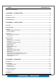
Page 6 E2 Wireless I/O TABLE OF CONTENTS 1 CHAPTER 1 – INTRODUCTION.........................................................................................8 1.1 Overview.........................................................................................................................................................8 1.2 Module Structure .........................................................................................................................................10 1.3 Getting Started.....
E2 Wireless I/O Page 7 4 CHAPTER 4 – CONFIGURATION ....................................................................................31 4.1 First time.......................................................................................................................................................31 Default Configuration.......................................................................................................................................31 Accessing Configuration for the first time...
Page 8 E2 Wireless I/O Chapter 1 – Introduction 1 1.1 Overview The E2 range of I/O modules has been designed to provide standard “off-the-shelf” telemetry functions, for an economic price. Telemetry is the transmission of data or signals over a long distance via radio or twisted-pair wire cable. Although the E2 Series is intended to be simple in its application, it provides many sophisticated features, which will be explained in the following chapters.
E2 Wireless I/O Page 9 Pulse inputs counts are accumulated and the total count is transmitted regularly according to the configured update time. The E2 modules transmit the input/output data using radio or Ethernet. The data frame includes the "address" of the transmitting module and the receiving module, so that each transmitted message is acted on only by the correct receiving unit.
Page 10 E2 Wireless I/O 1.2 Module Structure The E2 is made up of a number of basic sections, which all interface with a central Input and output storage area (I/O Store). The I/O Data Store provides storage for I/O data as well as providing services to other processes in the system. The I/O Store provides eight different blocks of data - two containing input and output bit data, two containing input and output word data, two containing long-word type data and two containing floating-point data.
E2 Wireless I/O Page 11 There are also a number of Internal I/O that can be accessed from the I/O Data Store. These inputs can be used to interpret the status of a single modules or the entire system • Supply voltage status – If the primary supply fails, this status is set on. • Low battery voltage – Monitors the internal battery charger to trickle charge a back-up battery. If the battery voltage is low, this status is set. • Battery voltage – The actual value of the connected battery voltage.
Page 12 E2 Wireless I/O Chapter 2 – Installation 2 2.1 General All E2 Series modules will be housed in a plastic enclosure with DIN rail mounting, providing options for up to 20 I/O points, and separate power & communications connectors. The enclosure measures 170 x 150 x 33 mm including connectors. The antenna protrudes from the top 2.2 Power/Supply The E2 power supply is of switch-mode design and will accept a 15 - 30 volt DC power source connected to the “Sup + & Sup -” terminals.
E2 Wireless I/O Page 13 The power supply input and battery charging are hosted on a 4-way terminal on the bottom edge of the module labeled “Power Supply”. To allow increased I/O Capacity, a second 4-way terminal labeled “Expansion I/O” provides a +12 Volt supply and RS485 communications for any 115S serial expansion I/O modules.
Page 14 E2 Wireless I/O Meshing capability The ELPRO WIBMesh protocol is based on the “Ad hoc On Demand Distance Vector” (AODV) routing algorithm which is a routing protocol designed for ad hoc networks. AODV is capable of unicast and multicast routing and is an on demand algorithm, meaning that it builds and maintains these routes only as long as they are needed by the source devices. The Protocol creates a table, which shows the connection routes to other device in the system.
E2 Wireless I/O 2.4 Page 15 Antenna The E2 module will operate reliably over large distances. The distance, which may be reliably achieved, will vary with each application - depending on the type and location of antennas, the degree of radio interference, and obstructions (such as hills or trees) to the radio path. Typical reliable distances are detailed below however longer distances can be achieved if antennas are mounted in elevated locations – such as on a hill or on a radio mast.
Page 16 E2 Wireless I/O At 900MHz the maximum net gain of the antenna/cable configuration permitted is Country USA / Canada Max. Gain (dB) 6 Australia / New Zealand 0 Europe 0 At 900MHz the gains and losses of typical antennas are Antenna Dipole with integral 15’ cable Gain (dB) 0 5dBi Collinear (3dBd) 5 8dBi Collinear (6dBd) 8 6 element Yagi 10 9 element Yagi 12 16 element Yagi 15 Cable type RG58 Loss (dB per 30 ft / 10 m) -5 RG213 -2.
E2 Wireless I/O Page 17 already shielded from lightning strike by an adjacent earthed structure, a lightning rod may be installed above the antenna to provide shielding. Dipole and Collinear antennas. A collinear antenna transmits the same amount of radio power in all directions - as such they are easy to install and use. The dipole antenna with integral 15 ‘cable does not require any additional coaxial cable; however a cable must be used with the collinear antennas.
Page 18 E2 Wireless I/O antennas should have vertical polarisation, and the common (or “central” station should have a collinear (non-directional) antenna. Also, note that Yagi antennas normally have a drain hole on the folded element - the drain hole should be located on the bottom of the installed antenna. 2.5 Connections Bottom panel connections Ethernet port The E2 modules provides a standard RJ-45 Ethernet port compliant to IEEE 802.3 10/100 BaseT.
E2 Wireless I/O RJ-45 Signal Name 1 2 3 4 5 6 7 8 RI DCD DTR GND RXD TXD CTS RTS Page 19 Required Y Y Y Y Signal name Ring Indicator Data Carrier Detect Data Terminal Ready Signal Common Receive Data (from Modem) Transmit Data (to Modem) Clear to Send Request to Send RS-485 port with Modbus Support. The E2 module provides an RS-485 serial port, which support operations at data rates up to 115,200 baud.
Page 20 E2 Wireless I/O “Factory Boot” switch The “Factory Boot” switch is used to allow restoration of the firmware to a module that has become non-functional. This switch should not normally be used, except if advised by ELPRO support. USB Host port This port is a USB Host (Master port), which allows interface with a USB storage device for data logging and for Firmware update to the module.
E2 Wireless I/O Page 21 to measure voltage on Analog input 4. Set switches ON to measure current on Analog input 4. Dipswitch 5 – Factory use only. This switch should be set to ON to enable the hardware watchdog protection feature. Dipswitch 6 – When set to ON, the module will boot up with a known factory default including a default IP address for Ethernet connection. (Refer to section 4.
Page 22 E2 Wireless I/O Pulsed Inputs The E2 supports 8 digital signals, of which inputs 1-4 can be used as pulsed inputs. The maximum pulse frequency is 50 KHz for Input 1 & 2 and 10 KHz for Input 3 & 4. Digital/Pulsed inputs are suitable for voltage-free contacts, or NPN-transistor switch devices.
E2 Wireless I/O Page 23 Digital Outputs (Pulsed Outputs) Digital outputs are open-collector transistors and are able to switch loads up to 30VDC, 200mA. The 8 digital outputs share the same terminals as the digital input. These terminals are marked DIO1-8. When active, the digital outputs provide a transistor switch to EARTH (Common). To connect a digital output, refer to the diagram across. A bypass diode is recommended to protect against switching surges for inductive loads such as relay coils.
Page 24 E2 Wireless I/O The Failsafe state if ticked (ON) will indicate with the LED being on and briefly flicking off. The Failsafe state if un-ticked (OFF) will indicate with the LED being off and briefly flicking on. Analog Inputs The E2 provides two floating differential analog inputs and two grounded single-ended analog inputs. Analog Input 1 & 2 can be configured to measurement current (0-20 mA) or Voltage (025V). Analog input 3 & 4 can be configured to measure current (0-20mA) or voltage (0-5V).
E2 Wireless I/O Page 25 Single Ended Current Inputs (AIN 3 & 4 only) Single-ended current input mode is useful if the sensor loop is grounded to the E2 module. Devices can be powered externally from the 24V Analog Loop Supply supplied internally within the module. The Dip Switches are used to determine if the inputs will be current or voltage. .
Page 26 Analog Outputs The E2 module provides two 0 - 24 mA DC analog outputs for connecting to instrument indicators for the display of remote analog measurements. The E2 Analog outputs are a sourcing output and should be connected from the analog output terminal through the device or indicator to Common. See diagram for connections.
E2 Wireless I/O Page 27 Chapter 3 – Operation 3 3.1 Overview The E2 range of I/O modules has been designed to provide standard “off-the-shelf” telemetry functions, for an economic price. Telemetry is the transmission of data or signals over a long distance via radio or twisted-pair wire cable. 3.
Page 28 E2 Wireless I/O I/O Indications LED Indicator Condition Meaning DIO 1-8 ORANGE Digital input ON DIO 1-8 FLASHING ORANGE – Mostly On Update Failure – Failsafe state On DIO 1-8 FLASHING ORANGE – Mostly Off Update Failure – Failsafe state Off AI 1 & 2 #1 ORANGE Analog input current indication AI 1 & 2 #2 ORANGE Analog input voltage indication AI 1 & 2 FLASHING ORANGE Duty cycle relative to the analog reading Slow =4mA, Fast=20mA AI3 & 4 ORANGE Analog input current / voltage ind
E2 Wireless I/O 3.
Page 30 E2 Wireless I/O 3.4 WIBMesh The ELPRO WIBMesh protocol is based on the “Ad hoc On-demand Distance Vector” (AODV) routing algorithm which is a routing protocol designed for ad hoc networks. AODV is capable of unicast (single addressed message) and multicast (Broadcast to all) routing and is an “on-demand” protocol, meaning that it builds and maintains these routes only as long as they are needed by the source devices. Another words the network is silent until a connection is needed.
E2 Wireless I/O Page 31 Chapter 4 – Configuration 4 4.1 First time The E2 has a built-in web server, containing web pages for analyzing and modifying the module’s configuration. The configuration can be accessed using Microsoft® Internet Explorer. Default Configuration The default factory configuration of the E2 is IP address192.168.0.1XX, where XX is the last two digits of the serial number (the default IP address is shown on the printed label on the back of the module) netmask 255.255.255.
Page 32 E2 Wireless I/O Open the side configuration panel and set the #6 Dipswitch to ON Switch to the ON position. This will always start the E2 with Ethernet IP address 192.168.0.1XX, subnet mask 255.255.255.0, gateway IP 192.168.0.1 and the radio disabled. Do not forget to set the switch back to the OFF position and restart the module at the conclusion of configuration. Power up the E2 module. Open “Network Settings” on your PC under Control Panel.
E2 Wireless I/O Page 33 Figure 1 – Welcome Webpage To resume normal configured operation when Configuration is complete, switch Factory Default dip-switch on the E2 to RUN and cycle power. Note: Security Certificates. Configuration of the E2 uses an encrypted link (https). The security certificate used by the E2 is issued by ELPRO and matches the IP address 192.168.0.100. When you first connect to the E2, your web browser will issue a warning that ELPRO is not a trusted authority.
Page 34 E2 Wireless I/O 4.2 Network Configuration You can view or modify Ethernet network parameters by selecting the “Network” menu. When prompted for username and password, enter “user” as the username, and “user” as the password in the password field (This is the factory default – See section 4.8 “Module Information” to change). If you have forgotten the IP address or password, the Factory Default switch may be used to access the existing configuration. Refer to section above for this procedure.
E2 Wireless I/O Page 35 Radio Interface IP Address The IP address of the E2 on its wired (Ethernet Interface) port and wireless (Wireless Interface) port. This should be set to the IP address you require. If the device mode is set to bridge, then the wired and wireless ports will have the same IP address. IP Subnet Mask The IP network mask of the E2 on its wired (Ethernet Interface) port and wireless (Wireless Interface) port.
Page 36 E2 Wireless I/O Radio Settings Transmit Power Level This allows adjustment of the radio power. Do not set the radio power above the allowed setting for your country You can reduce the power for short range applications, or to allow the use of high gain transmitter antennas while still complying with the emission requirements of your country.
E2 Wireless I/O 4.4 Page 37 WIBMesh Configuration The “TX Attempts for Acknowledged messages” is now many times the configured module will attempt to communicate a message to another module (message reties). After failing to communicate the module will be flagged as being in comms fail. Every time it tries to communicate to the remote module, it will reduce the number of attempts down to one as it has been flagged as being in Comms fail.
Page 38 E2 Wireless I/O 4.5 WIBMesh Mappings Selecting WIBMesh Mappings from the right hand side of the main menu will show the I/O Configuration screen. This is where you configure Read, Write and Gather/Scatter mappings as well as any Sensitivity Blocks. Write Mappings Add or delete mapping by using the buttons then select “Save and Activate Changes”. Block Write Mapping Destination IP Ack Invert This is the IP address that you wish to write the I/O to.
E2 Wireless I/O COS Enabled COS Resets Update Timer Force Reg Fail Reg First Local Reg First Remote Reg Reg Count Page 39 Can enable or disable the COS message. If disabled messages would only be sent on the update period. Enabling this timer will mean If a COS is received in between update messages it will reset the Update timer, meaning it will not receive another update until the further Update period has passed.
Page 40 E2 Wireless I/O Update Offset Response Timeout Force Reg Fail Reg First Local Reg First Remote Reg Reg Count Allows an offset to configured for each mapping. Used to stagger the transmissions so on start-up the module does not try to read all mapping at the same time. Default it will be 0 however the normal would be around 10 minutes Time before a response Failure is registered Register location that when written to will force the Read Mapping to be sent. E.g.
E2 Wireless I/O Update Offset COS Delay COS Enabled COS Resets Update Timer Force Reg Fail Reg Reg Count Page 41 Allows an offset to configured for each mapping. Used to stagger the transmissions so on start-up the module does not try to send all mapping at the same time. Default it will be 0 however the normal would be around 10 minutes You can enter a delay period such that the message is delayed from sending for the configured time.
Page 42 E2 Wireless I/O 4.6 Serial Configuration The E2 has an RS-232, and RS-485 port for serial communications. These ports may be used to connect external Modbus RTU devices via the Modbus TCP to RTU Gateway. Modbus TCP to RTU Gateway The Modbus TCP to RTU Gateway allows an Ethernet Modbus/TCP Client (Master) to communicate with a serial Modbus RTU Slave. The E2 makes this possible by internally performing the necessary protocol conversion.
E2 Wireless I/O Page 43 RS232 / RS485 Serial Port Configuration RS232 Port Select the desired functionality. Select either Serial Gateway or Modbus TCP to RTU Data Rate The serial data rate desired. Serial data rates available range from 110bps to a maximum of 230,400bps. Data Format The data format desired. All the standard data formats are supported.
Page 44 E2 Wireless I/O 4.7 I/O Configuration Analog Inputs The following configuration parameters are available on the E2 Analog inputs Name – Can re-name the inputs or use the default, up to 30 characters including spaces. Zero / Span – These variables will change the Scale of the Analog Inputs. Filter (sec) – The Filter time is the time for the analog to reach 63% of its settled value on a step change. By default the Pulsed inputs are not filtered.
E2 Wireless I/O Page 45 Deadband - If the Analog Input is less than the Lower Set point, the set-point status will be active (on, “1”) and remain active until the Analog Input is greater than the Upper Set Point, the set-point status will be reset (off, “0”). Note that the Upper Set Point must always be higher than the Lower Set Point. Windowed –The Upper and Lower sets are used to setup a “window” within the analog range.
Page 46 E2 Wireless I/O Digital Input Name – Can re-name the inputs or use the default, up to 30 characters including spaces. Debounce Time (sec) – Debounce is the time which an input must stay stable before the module decides that a change of state has occurred. If a digital input changes (on off) and changes again (off - on) in less than the debounce time, then the module will ignore both changes. Default debounce time is .5 seconds.
E2 Wireless I/O Page 47 4.8 Module Information This configuration page is primarily for information purposes. With the exception of the password, the information entered here is displayed on the home configuration webpage of the E2. Username Configuration of Username. This is the username used to access the configuration on the E2. Take care to remember this username if you change it as it will be needed to access the E2 in future. Password Configuration of Password.
Page 48 E2 Wireless I/O 4.9 System Tools This screen is where you can log system instructions, etc to the screen and from there you can save to a file. This screen also is where any uploading and saving of the configuration is done. Reading Configuration File Reads the module configuration into an XML file for saving.
E2 Wireless I/O Page 49 These files are mapped into the address map as described below.
Page 50 30009 30012 30013 30016 40001 40002 E2 Wireless I/O Local AI1 – AI4.
E2 Wireless I/O Page 51 Chapter 5 – Diagnostics 5.1 IO Diagnostics By selecting this option on the main screen will allow some basic reading and writing of the I/O store within the module. To read a location, enter an address location, e.g.
Page 52 5.2 E2 Wireless I/O Diagnostic Information Connectivity The Connectivity webpage displays connections and available networks. The “Connected Devices” section displays the radio channel, received signal strength, and radio data rate for each Client or Access Point by their MAC Address. The readings shown are based upon the last received data message from the Access Point or Client.
E2 Wireless I/O Page 53
Page 54 E2 Wireless I/O Appendix A 5 Appendix A I/O Store 6 “Output Coils” 0001 0008 0009 0020 0021 0040 0041 0500 Local DIO1 – DIO8 (as Outputs) at address 1-8.
E2 Wireless I/O Page 55 10596 Message Buffers Exhausted Alarm 10597 Message Buffers Exhausted Alarm Latch 10598 Spare 10599 Spare 10600 Spare 10601 General Purpose Bit Storage – Used for: • Staging area for data concentrator • Fieldbus Mappings storage 12500 12501 30000 Not Available “Input Registers” 30001 30004 30005 30006 30007 30008 30009 30012 30013 30016 30018 30020 30021 30040 Local AI1 – AI4. (Current Mode) ( AI1, AI2 4-20mA diff.
Page 56 E2 Wireless I/O 30599 Spare 30600 Spare 30601 General Purpose word Storage – Used for: • Staging area for data concentrator • Fieldbus Mappings storage 32500 32501 36000 36001 36008 36009 36040 36041 38000 Not Available Local Pulsed inputs 1-4.B.E Format. Most significant word at lower / odd address. spare Not Available 38001 Local Analog inputs as floating point values Modscan Format (Sign + Exponent + Most significant 7 bits of significant at Even / Higher Addressed location.
E2 Wireless I/O Page 57 40500 40501 42500 42501 46000 46001 46008 46009 46040 36041 38000 General Purpose word Storage – Used for: • Staging area for data concentrator Fieldbus Mappings storage Not Available Local Pulsed Outputs 1-4. B.E Format. Most significant word at lower / odd address. spare Not Available 48001 Local Analog outputs as floating point values Modscan Format (Sign + Exponent + Most significant 7 bits of significant at Even / Higher Addressed location.