
User's Manual


Chapter One Introduction
man_905_2.1.doc Page 9
unlicensed operation for remote monitoring and control of equipment. That is, a radio licence is not
required for the modules in many countries. See Chapter Five Specifications for details.
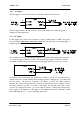
Input signals connected to a module are transmitted to another module and appear as output
signals. These input signals may also be configured to appear as “inverted” signals on the output. A
transmission occurs whenever a "change-of-state" occurs on an input signal. A "change-of-state" of
a digital or digital internal input is a change from "off" to "on" or vice-versa. A "change-of-state" for
an analogue input, internal analogue input or pulse input rate is a change in value of the signal of 3%
(configurable from 0.8 to 50 %).
In addition to change-of-state messages, update messages are automatically transmitted on a regular
basis. The time period may be configured by the user for each input. This update ensures the
integrity of the system.
Pulse inputs are accumulated as a pulse count and the accumulated pulse count is transmitted
regularly according to the configured update time.
The modules transmit the input/output data as a data frame using radio or serial RS485 as the
communications medium. The data frame includes the "address" of the transmitting module and the
receiving module, so that each transmitted message is acted on only by the correct receiving unit.
Each transmitted message also includes error checking to ensure that no corruption of the data frame
has occurred due to noise or interference. The module with the correct receiving "address" will
acknowledge the message with a return transmission. If the original module does not receive a
correct acknowledgement to a transmission, it will retry up to five times before setting the
communications fail status of that path. In critical paths, this status can be reflected on an output on
the module for alert purposes. The module will continue to try to establish communications and
retry, if required, each time an update or change-of-state occurs.
A telemetry system may be a complex network or a simple pair of modules. An easy-to-use
configuration procedure allows the user to specify any output destination for each input.
The maximum number of modules in one system is 95 modules communicating by radio. Each of
these modules may have up to 31 other modules connected by RS485 twisted pair. Modules may
communicate by radio only, by RS485 only or by both RS485 and radio. Any input signal at any
module may be configured to appear at any output on any module in the entire system.
Modules can be used as repeaters to re-transmit messages on to the destination module. Repeaters
can repeat messages on the radio channel, or from the radio channel to the serial channel (and serial
to radio). Up to five repeater addresses may be configured for each input-to-output link.
The units may be configured using switches under the plastic cover on the front of the unit or by
using a PC connected to the RS232 port. The default configuration is defined in Section 4.2 Easy
Configuration Using Default Settings, and software configuration is defined in Section 4.2
Configuration Software . Several standard configurations are also available. These are described
in the separate Switch Configuration Manual, available from your distributor.