
User manual


Chapter Three Operation
Page 51 © April 2007
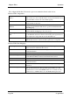
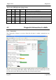
The configurable Modbus I/O transfer options are summarized in the tables below.
Modbus TCP Configuration:
Enable Modbus TCP Server
(Slave)
Check this box to enable the onboard Modbus TCP Server. All Modbus
TCP connections to the module IP Address and specified Modbus Server
Device ID will be routed to the onboard I/O registers.
Modbus Server Device ID Specify the Modbus Device ID for the onboard Modbus TCP Server.
Allowed values are 0 to 255.
Enable Modbus TCP Client
(Master)
Check this box to enable the onboard Modbus TCP Client. I/O to be
transferred via the Modbus TCP client is specified with Modbus TCP
Client Mappings.
Modbus Client Scan Rate Enter the delay (in milliseconds) between execution of consecutive
Modbus TCP Client Mappings to the same Server.
Reset Registers on Comm’s
Fail
When Enabled the value in any onboard I/O register will be reset to zero
if a valid Modbus transaction directed to/from the given register has not
been completed for longer than the Comms Fail Timeout.
Comms Fail Timeout The period of time after which onboard I/O registers will be reset if a
valid Modbus transaction directed at that register has not completed.
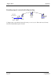
Modbus TCP Client Mappings:
Local Register Enter the starting onboard I/O register number that the specified Modbus
Master transaction will transfer I/O to/from.
I/O Count Specify the number of consecutive I/O register to be transferred for the
specified transaction.
Function Code Specify the Modbus Function Code for the transaction.
Destination Register Enter the starting I/O register number in the destination device that the
specified Modbus Master transaction will transfer I/O to/from.
Device ID Enter the Modbus Device ID of the destination Modbus device
Server IP Address Specify the IP Address of the destination Modbus TCP Server for the
specified transaction.
Response Timeout Enter the timeout (in milliseconds) to wait for a response to the specified
transaction.
Comm Fail Register Enter the onboard I/O Register number to store the communication status
of the specified transaction. The Specified register will be set to 0 if
communications is successful, 0xFFFF if there is no connection to the
specified server, or 0xFFxx where xx is the Modbus Exception Code