
User manual


Chapter Three Operation
Page 55 © April 2007
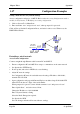
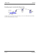
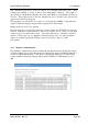
Connecting two separate networks together
Network A Configuration
In this example, network A is connected to the internet via a router at IP address 192.168.0.1.
Devices on Network A that only require access to devices on Networks A and B, should have
their gateway IP address set to the 805U-E Access Point as 192.168.0.200.
Devices on Network A, that must interact with devices on Networks A and B and the internet
should set the internet router 192.168.0.1 as their gateway, and must have a routing rule
established for devices on Network B. On PCs, this may be achieved with the MS-DOS
command ROUTE. For this example use: ROUTE ADD 192.168.102.0 MASK
255.255.255.0 192.168.0.200
Network B Configuration
All devices on Network B should be configured so their gateway IP address is that of the
805U-E Access Point as 192.168.102.54
Access Point Configuration
• Connect straight through Ethernet cable between PC and 805U-E.
• Ensure configuration PC and 805U-E are setup to communicate on the same network
• Set dipswitch to SETUP
• Power up unit, and wait for LINK led to cease flashing.
• Adjust PC network settings
Set Configuration PC network card with network setting of IP address 192.168.0.1,
netmask 255.255.255.0
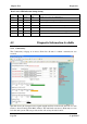
• Open configuration webpage with Internet Explorer at address http://192.168.0.1XX/
When prompted for password, enter default username “user” and password “user”
Enter “Quick Start”, and select Access Point.
Change the IP address to 192.168.0.200
Enter a System Generator String
Select the Radio Encryption required.
Set dipswitch to RUN.
Save the changes, and unit will reset. Wait for unit to complete reset.
• Open configuration webpage with Internet Explorer at address http://192.168.0.200/
LAN A
Internet
Client
Bridge
Access Point
Router
192.168.0.0
255.255.255.0
169.254.102.54
LAN B
169.254.102.53
169.254.102.50
255.255.255.0