E2-455 User Manual User Manual for E2-455 Licensed Radio man_E2-455_V1-7.docx E2-455 Radio Module OEM/Integrators Installation Manual Page 1 of 14 man_E2-455_V1-7.
E2-455 User Manual ATTENTION! Incorrect termination of the supply wires may cause internal damage. Before turning the power on double-check ALL connections by referring to this User Manual. CAUTION To comply with FCC RF Exposure requirements in section 1.1310 of the FCC Rules, antennas used with this device must be installed to provide a separation distance from all persons as described in section “Safety Notices” below to satisfy RF exposure compliance.
E2-455 User Manual FCC (USA) Exposure to RF energy is an important safety consideration. The FCC has adopted a safety standard for human exposure to radio frequency electromagnetic energy emitted by FCC regulated equipment as a result of its actions in Docket 93-62 and OET Publication KDB 447498 D01. Depending on antenna type, ensure the following minimum separation distances from antennas for (A) Occupational and (B) General Population.
E2-455 User Manual YU3/400 + CC10/450 0.38 1.07 YU6/400 + CC10/450 0.53 1.51 YU9/400 + CC20/450 0.45 1.27 YU16/400 + CC20/450 0.79 2.26 Limitations and Condition of Use: ELPRO E2-455 radio module is designed as a reusable module for use with future development of ELPRO products. The module is limited for use by ELPRO only. This module is not to be made available for third party use or in any OEM arrangements.
E2-455 User Manual 1 Introduction The E2-455 is a radio modem module used as a base radio for a number of Elpro wireless products, with additional products to be added in the future. It operates as a wireless network adapter for transfer of 802.11 format data frames over lower speed wireless links. The E2-455 consists of a host microcontroller, an RF transceiver section, and a power supply section.
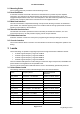
E2-455 User Manual 2.1 Mounting Points Four mounting points are provided for 2.5mm Mounting screws. 2.2 Heat-Sink Block A Heat-Sink should be connected to the device’s Heat-Sink block to prevent the power amplifier overheating. The interface to the Heat-Sink block uses two M3 screws separated by 15mm, with engagement depth between 3mm-4mm. Use heat-paste or other heat-conducting material to provide an effective heat conduction path from the heat-sink block to the supplied heat-sink. 2.
E2-455 User Manual 3.2 Canada Locale The following restrictions on each of the bands apply when Canadian Locale is selected: Locale Frequency Band Supported Channel Bandwidth RSS-119 148.000MHz -149.900MHz 6.25kHz, 12.5kHz, 25kHz RSS-119 150.050MHz – 174.000MHz 6.25kHz, 12.5kHz, 25kHz RSS-119_B1 421.000MHz – 430.000MHz 6.25kHz, 12.5kHz RSS-119_B2 450.000MHz – 470.000MHz 6.25kHz, 12.
E2-455 User Manual Save Configuration (save all cfg and par items except for rate). > cfg save Reset unit. > reset To change rx/tx monitor). > mon frm info Shows more information > mon frm head Shows less information 4.1.2 Radio Transmit Commands Set Transmit Power for Test commands. > par txpwr 27 [1] Transmit power = 27 dBm Note: Maximum power is limited according to supply voltage and modulation selected. Power drops by 3dB at approximately 12V supply.
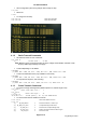
E2-455 User Manual [1] RX_CTS_OTH = 0 [1] RX_CTS_ME = 0 [1] RX_ACK_OTH = 0 CTS to other / Me [1] RX_ACK_ME = 0 ACK to other / Me [1] RX_UNSPRT = 0 Unsupported Frame Type Multicast Frame [1] RX_MULTI = 0 [1] RX_UNI_OTH = 0 [1] RX_UNI_ME = 0 Unicast message to other / Me To count the number of received frames, add RX_RTS, RX_CTS, RX_ACK, RX_UNSPRT, RX_MULTI and RX_UNI types. When testing with command “frm rad raw”, all received frame should be RX_UNSPRT.
E2-455 User Manual 4.3.2 General Message Format Table 1 describes the general format of the messages including the start and end flags. START_FLAG 1 byte Start of message identifier (0x7E) Service_code 2 bytes Service code to identify message type and message ID Payload Data 0-n bytes Message payload data. Interpreted according to Service code END_FLAG 1 byte End of message identifier (0xFF) Table 1 4.3.
E2-455 User Manual 5 Host Interface Hardware Description This section describes the interface to the host, including the two alternate power/data interfaces and the earthing connections. 5.
E2-455 User Manual 9 MB_CSF Future Use – Do Not Connect Output from module 10 CTS0_7 Clear to send (When toggled, it indicates that the host should wake up.) Output from module 11 MBIRQ Future Use – Do Not Connect Input to module 12 RTS0_7 Ready to Send (When toggled, it indicates that the radio processor should wake up.
E2-455 User Manual 6 Specifications Environmental Operating Temperature -40°C to +70°C (-40 to +120°F) Humidity 0-95% Non-Condensing Altitude 0-2000m / 6500ft Radio General Half Duplex UHF radio supports operation on Licensed and Unlicensed bands. RF Bands Channel Spacing 6.25kHz, 7.5kHz, 12.5 kHz, 20kHz, 25 kHz Supported Frequency Bands 148-174MHz 340-400MHz 400-480MHz 470-520MHz Antenna Transmitter Data Rates Single SMA Connector for Receive and Transmit.
E2-455 User Manual 7 REVISION HISTORY Issue No. Date Details of Amendment 1.0 24/10/2017 Initial Issue – From E2-450 User Manual 1.1 04/02/18 Update Safe distance limits 1.2 08/03/18 Update Safety notices to include Canada (ISED) specific RF exposure limits. 1.4 22/03/18 Update after CB Review. Notes re OEM installation, application notes. Note on Antenna connectors. Update FCC Exposure table. 1.5 08/05/18 Updates after CB review. Added Canada Locale details. 1.