Home Integrated System Wireless Security & Home Automation System Installation & Operating Manual
CONTENTS KIT CONTENTS 1 Testing the Wall Switch 15 INTRODUCTION AND OVERVIEW Multiple Users System Arming Zones Entry/Exit Delay Quick Set Zone Lockout Event Log Chime Voice Dialer Digital Dialer Latch Key Remote System Control Tamper Protection Jamming Detection Battery Monitoring ID Code Learning Home Automation Distance Control & Feedback Backup & Restore 2 2 2 2 2 3 3 3 3 3 3 3 3 3 3 4 4 4 4 4 EXTERNAL CONNECTIONS 16 TESTING THE SYSTEM Initial Testing Testing an Installed System Walk Test RF Env
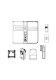
included in the package. KIT CONTENTS The Alarm System should contain the following components. For HIS20S 1 x Smart Home Box 1 x Wireless Key 1 x PIR Detector 1 x Remote Control 1 x Magnet Contact Detector 1 x On/Off Receiver 1 x Wall Switch HIS20 Smart Home Box Fixing pack: 2 x 15V/1.2Ahr Sealed lead acid battery 2 x 3.
INTRODUCTION AND OVERVIEW ZONES MULTIPLE USERS The system incorporates 32 wireless Alarm Zones for the connection of the system detectors that are used to independently monitor different areas of the property. In addition to standard intruder protection, each zone may also be configured to operate in one of four modes: The system allows for up to 7 Users and an Administrator to be configured. This allows the system Event Log to maintain a record of which users have armed and disarmed the system.
QUICK SET DIGITAL DIALER The system may be fully armed in 5 seconds using the quick set facility, overriding the programmed exit-delay. This is useful for setting the system at night when the exit-delay warning beep will be silenced after just a few seconds. As an alternative to the Voice dialer the system may be configured to interface with a central monitoring station.
DISTANCE CONTROL & FEEDBACK a 5 minute interval, this will also generate a Full Alarm condition. You can achieve the controlling function of enhanced devices (i.e. devices with 868MHz radio frequency) via GSM Gateway or IP Gateway if they are enabled. If alarm condition occurs, the SMS message/mail will be transmitted to you as a warning report. The jamming detection features in the Smart Home Box and Solar Siren operate independently.
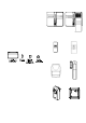
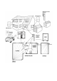
PLANNING AND EXTENDING YOUR WIREFREE ALARM SYSTEM Home Box, PIR, Magnetic Contact Detectors and Wall Switch for optimum security and home automation. You can use this as a guideline for planning your intruder alarm and home automation system. The following example shows a typical property incorporating the suggested positions for the Smart Smart Home Box Before attempting to install Alarm System, it is important to study your security requirements and plan your installation.
REMOTE CONTROL UNIT 4. In order to communicate with the Smart Home Box, the ID code of the Remote Control needs to be learned by the Smart Home Box. a. Set the Smart Home Box into ‘1. User Setup’ and press . b. Select which administrator/user will carry the remote control and press . c. Select ‘:7 Remoter’ and press . d.
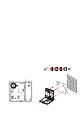
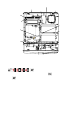
connecting to a telephone master or secondary outlet. Battery 1 (upper): Blue lead to +ve battery terminal Black lead to –ve battery terminal 7. Do not locate the Smart Home Box closer than 1m to any large metallic object, (e.g. mirrors, radiators, etc) as this may affect the radio range of the Smart Home Box.
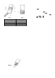
Keyhole Slot Keyhole Slot +ve Terminal (Blue Lead) -ve Terminal (Black Lead) Terminal Block Hardwire Siren Tamper Return Link P51 +ve Terminal (Red Lead) Reset Jumper Link P1 -ve Terminal (Blue Lead) Power Supply Jack Socket Inside View of Smart Home Box TESTING THE SMART HOME BOX & REMOTE CONTROL the ‘DISARM’ button on the Remote Control from in and around the property and from all locations where you plan to install detectors.
When considering and deciding upon the mounting position for the detector the following points should be considered to ensure trouble free operation: The PIR Detector adopts a 1/2 AA size 3.6V Lithium battery which under normal conditions will have typical life in excess of 4 years. When the battery level drops, with the PIR in normal mode and the battery cover fitted, the LED behind the detection window will flash upon detecting movement.
7. To refit the PIR detector to the rear cover and locate the clips in the top edge into the rear cover. Push the lower edge of the detector into place and refit the fixing screw in the bottom edge of the PIR to secure in position. Do not over-tighten the fixing screws as this may damage the casing. 2. Carefully drill out the required mounting holes in the rear cover using 3mm drill according to whether the unit is being mounted in a corner or against a flat wall.
the Smart Home Box. To proceed with ID code learning. Set the required sensitivity detection using DIP2 of SW2 as follows: ON OFF a. Set the Smart Home Box into ‘3. Security Sensor Zone’ and press . b. Select ‘3-1 Wireless Sensor Zone’ and press . c. ‘Input (01-32) Sensor Zone’ and press . d. An indication of ‘:1 Learning ID’ will be shown and press .
magnetic field, trigger the Detector and generate an alarm condition, (if the system is armed and the alarm zone active). 1. Press , , to put the system into Test mode. ‘WALK TEST’ will be displayed. The Detector is powered by one 3.6V 1/2 AA size Lithium cells which under normal conditions will have typical life in excess of 5 years. Under normal battery conditions with battery cover fitted the LED on the Detector will not illuminate when the Detector is triggered, (unless in test mode).
2. Fit the 3.6V Lithium battery supplied, with the negative (-) towards the battery spring. 3. Mount the Detector to the fixed part of the frame along the opening edge opposite the hinges using either the double sided adhesive tape or screws provided. 2. DIP switches 1-2 are used to enable/disable the internal or external wired magnetic contact. If fixing the Detector with screws; fit the Keyhole slot in the top of the Detector over the head of the smaller pan-head screw.
to put the system into Test mode. ‘WALK TEST’ will be displayed. b. Select ‘3-1 Wireless Sensor Zone’ and press . c. ‘Input (01-32) Sensor Zone’ and press . d. An indication of ‘:1 Learning ID’ will be shown and press . 2. Press to activate Walk Test. ‘ Walk Test Waiting…’ will be displayed. 3. By pressing tamper switch either located adjacent to the PCB or rear cover of the Detector will emit the ID code to the Smart Home Box instantly. 5.
status of the plug-in light fixtures or home appliances without controlling via Smart Home Box. LEARNING ID CODE In order to communicate with the Smart Home Box, the Smart Home Box will send ID code to the receiver. To proceed with ID code learning: On/Off Knob 2. By pressing the wall switch, the LED will illuminate, implying that the battery has been inserted properly. LED Indicator 1. In the front cover, there is an On/Off knob with LED indicator. 2.
1. Press , , to put the system into Test mode. ‘WALK TEST’ will be displayed. 2. Press to activate Walk Test. ‘ Walk Test Waiting…’ will be displayed. 3. By pressing ON or OFF knob each time, the Smart Home box will chime in response. EXTERNAL CONNECTIONS The Smart Home Box incorporates a terminal block for connection of hard-wired Zones (33-36), Siren or Telephone Dialer unit. The connection terminal block is located inside the Smart Home Box behind the front cover.
TESTING THE SYSTEM INITIAL TESTING Press , User Password As the system is initially installed it is recommended that each device is tested in turn as it is installed, (refer to testing instructions for particular device). This puts the system into Test Mode. TESTING AN INSTALLED SYSTEM Use the The Smart Home Box has a programmed test routine. the menu and press You may test the system at any time, however it is test function or sub-menu.
Press to exit Walk Test and return to the top press . level Test Mode menu. This offers the flexibility of removing or changing siren’s RF ENVIRONMENT TEST battery. Wait for 10 seconds until ON/OFF duration Scroll through the top level Test Mode menu until ‘RF has elapsed, then go ahead with fixing the siren as desired. Environment ’ is displayed. ALARM TEST If the ambient environment is full of radio frequency, an Scroll through the top level Test Mode menu until indication of ‘ENVIRON . .
Night Alarm Key Tone Back Light Error Beep Auto Report Function RF Jamming Detection Alarm Relay Zone Lock Exit Delay Exit Delay Beep Entry Delay Entry Delay Beep Date dd/mm/yy Time hh:mm:ss Wirefree Keypad Event & Schedule ON ON 20s 30s 12h OFF On Until Disarm ON 30s ON OFF OFF 1/1/2011 Sat.
Backup & Restore 9. Close the Smart Home Box cover and refit the Backup Today’s DD/MM/YY Restore Not Programmed fixing screws. Note: please always remember the next step you RESET should carry out after resetting the Smart Home Box is ID code learning for each device. After carrying out the following steps, the Smart Home Box will not return to factory default, instead, the memory of any settings and learnt devices (e.g.
PROGRAMMING INSTRUCTIONS Note: Programming is only available under Disarm With the system in Disarm Mode. Mode. While you are using the PC to do the program setting, the keypad on the Smart Home Box will Press , , become inactive unless you press for 3 seconds. Admin Password The system is now in the Programming Mode After programming all required functions press Use the to leave Programming mode and return to Disarm and buttons to scroll through the programming menu.
LATCHKEY REPORT It is useful for a parent at work who wants to be sure that his children have returned from school and have disarmed the system. A special ‘latchkey’ message will be sent out to the user of first telephone number when the system is disarmed by a ‘latchkey user’. display once the system is armed/disarmed by the particular user. The maximum memorized capacity for each user name is 15 digits. Scroll through the menu until ‘:2 Name’ is displayed. To change the setting press .
Code Learning Pressing , or Scroll through the menu until ‘:7-4 Del data’ is displayed. button on the remote control will enable the Smart Home Box to learn the ID code. To change the setting press Scroll through the menu until ‘:7-1 Learning ID’ is displayed. . Press Press to delete the remote control setting, or to keep the same setting.
HOME BOX SETUP PROGRAM MODE Code: 2. Home Box Setup 2-1 Alarm Time xxx Sec. 2-3 EXT. Siren :3-1 Wire Siren 10SEC 30SEC 1MIN 3MIN 5MIN 10MIN 2-4 Key Tone xx :3-2 Wirefree Siren Select ON->* OFF-># :3-3 Night Alarm Select ON->* OFF-># Select ON->* OFF-># ;2-1 Code Setup 2-5 Back Light xx SEC. 2-6 Error Beep xxx SEC. 5SEC 10SEC 20SEC 30SEC 60SEC 10SEC 30SEC 1MIN 2MIN 4MIN OFF ;2-2 Siren Working:xx 2-2 INT.
Scroll through the top level programming menu until ‘2. HOME BOX SETUP’ is displayed and press . To change the setting press Press Press Note: After completing the system setup press to return to the top level programming menu. Code Learning The wireless siren has a row of 8 DIP switches. In order to communicate with the Smart Home Box properly, the house code for the wireless siren needs to be learned by the Smart Home Box.
Scroll through the menu until ‘2-6 Error Beep’ is displayed. The current setting will also be displayed. KEY TONE This feature, if enabled, allows the Smart Home Box to sound a tone each time the keypad is pressed. To change the setting press Default setting: ON Scroll through available options, (10SEC, 30SEC, 1MIN, 2MIN, 4MIN and OFF) until the required setting is displayed and then Scroll through the menu until ‘2-4 Key Tone’ is displayed. The current setting will also be displayed.
Press Press ALARM RELAY This setting controls the operation period for the NO/NC hardwired output relay contacts following an alarm condition being initiated. to save and exit, or to exit without saving. If this is set to ‘ON Until Disarm’ then the relay will latch and remain On until the system is next disarmed. EXIT DELAY BEEP This controls the warning beep which operates during the Exit Delay period when Arm is initiated. Scroll through the menu until ‘2-9 Alarm Relay’ is displayed.
Press Press ID Duplicate – the same ID code was learned by the Smart Home Box beforehand. to enable the Entry-delay beep, or to disable the Entry-delay beep. DATE This feature is for setting of local date. Default setting: 1/1/2011 Sat Keypad Off Scroll through the menu until ‘:2 Keypad Work: xxx’ is displayed and press . Scroll through the menu until ‘2-15 Date’ is displayed and press . Press Press Enter the date in the format ‘DD/MM/YY’. Press Press to save and exit, or to exit without saving.
SECURITY SENSOR ZONE SETUP PROGRAM MODE Code: 3.
This section is for setting of adding and categorizing of Scroll through available options until the required security devices (e.g. PIR detector). setting is displayed. Scroll through the programming menu until ‘3. SECURITY SENSOR ZONE’ is displayed and press . Enter the sensor zone number to be configured and press . Press to save and exit, or Press to exit without saving. MODEL Each detector can be defined as one of model types. Scroll through the menu until ‘:3 Model Type’ is displayed.
- used to provide Fire/Smoke 24-hour detectors monitoring fitted to the of any NIGHT ARM system. This facility controls whether the sensor zone is active Activation of any detector will immediately initiate a when the system is set to night arm. Full Alarm condition. Default setting: OFF Panic/PA - used to provide 24-hour monitoring emergency being occurred. of Scroll through the menu until ‘:6 Night Arm’ is any displayed. The current setting will also be displayed.
Press Detector. to disable the Magnetic Contact Press to keep the latest setting without changing. AUTO REPORT SIREN AT TRIGGER This feature, if enabled, allows the detector to give This decides whether the Smart Home Box will sound feedback to the Smart Home Box periodically with its or become silent when the sensor is triggered. latest status.
PHONE/LINE SETUP PROGRAM MODE Code: 4. Phone/Line 4-1 Voice Dial Setup :2 Record Voice :1 Voice Dial xxx On>* Select Off-># :2-1 Main Message :2-2 Intruder :2-3 Fire :2-4 Panic/PA Select Start->* Stop-># Select Start->* Stop-># Select Start->* Stop-># Select Start->* Stop-># :3 Play Voice :3-1 Main +Intruder :3-2 Main +Fire :3-3 Main +Panic/PA Playing… Stop->ESC Playing… Stop->ESC Playing… Stop->ESC 4-2 Monitor Center Setup :1 Monitor Center: xxx :2 Phone No.: :3 Unit ID NO.
required message type is displayed. Scroll through the programming menu until ‘4-1. Voice Dial Setup’ is displayed and press . a) Main + Intruder Messages b) Main + Fire Messages c) Main + Panic/PA Messages Note: After completing the Phone/Line Setup press to return to the top level programming menu. To replay the message press . VOICE DIALER This feature, if enabled, allows the enforcement of Press menu. voice dialer.
Press Enter the required number (1-5). to delete the character under the cursor. Press and hold Press Press to erase the entire phone number. to save and exit, or to exit without saving. displayed. The current setting will also be displayed. ARM/DISARM BY USER This determines when user makes a selection for disarming (Open) or arming (Close) the system, an event code 401 is needed to be sent to the central monitoring station.
Flow Chart for Control Call Routing Sequence (Monitor Center) Timeout 30 seconds Wait to enter ‘º’ 30 Sec Begin Event Trigger YES Hang up the phone End KEY =‘º’ Dial Preset TEL No.
Enter the required number of ring (2-9). NUMBER OF DIALING CALL This facility controls the number of dialing call via the connected telephone line. Press to save and exit, or Press to exit without saving. Default setting: one call INTERVAL OF RING FOR DOUBLE CALL Scroll through the manual until ‘:1 Remote Type’ is The interval of ring in each country varies greatly. displayed and press Always add extra 2s to your countries’ interval of ring. . To change the setting press .
NOTIFICATION SETUP PROGRAM MODE Code: 5. Notification Setup 5-1 Set TEL No.
NOTIFICATION SETUP Scroll through the programming menu until ‘5. Press Notification Setup’ is displayed and press sending SMS, or . Press Note: After completing the Notification Setup press to enable the function of dialing and to disable the function of dialing and sending SMS. to return to the top level programming menu. TELEPHONE NUMBERS Level 1 Scroll through the menu until ‘5-1 Set TEL NO.
To change the setting press Enter the required number (1-6). Press Press Press Press to save and exit, or to exit without saving. . to enable Call Abort, or to disable Call Abort. Event Trigger DIAL ROUND This sets the maximum number of times that the dialer will attempt to contact each enabled telephone number in the call routing sequence. Dial Preset TEL No. Play trigger message Default setting: 3 NO Scroll through the menu until ‘5-3 Dial Round’ is displayed.
GREEN HOME SETUP PROGRAM MODE Code: 6. Green Home 6-2 Green Remote/Sensor 6-1 Green Control Input (1-32) Device Number Input (1-32) Cont.
Green Home setting is designed specially for home automation types of devices, i.e. device with 433 MHz radio frequency. Scroll through the top level programming menu until ‘6. GREEN HOME’ is displayed and press . Default setting: off To change the setting press Note: To return to top level programming menu, press . . Press to enable the devices, or Press to disable the devices. Note: Please pay attention to the appliance that is connected to the green control.
Scroll through available options, (Curtain Switch, Code Learning Dimmer and Switch Device ) until the required model This enables the Smart Home Box learns ID from Green Remote/Sensor. type is displayed and then Press Press to save and exit, or to exit without saving. Scroll through the menu until ‘:1 Learning ID’ is displayed and press . Note: If model type is selected incorrectly, the device will not function properly.
Press to retain the device. RECORD SCENE VOICE This voice record is set for scene, event and schedule. Scroll through the menu until ‘6-3 Record Scene Voice’ is displayed and press . Scroll through the menu until the required number of voice to be recorded is displayed and press Press to start recording or Press to stop recording. . Note: the record time is 4 seconds.
ENHANCE SETUP PROGRAM MODE Code: 7. Enhance :1 Model Type xxxx Learning ok 7-1 Enhance Device 7-2 GSM Gateway SMS Remote: xxx Input (01-12) E Device NO.
Enhance setting is designed specially for transceiver type of devices, i.e. device with 868 MHz radio frequency. Press to enable the device, or Press to disable the device. Note: ON implies enable whereas OFF implies disable. Scroll through the top level programming menu until ‘7. Enhance Device’ is displayed and press . The default setting will change to ON automatically once code learning is completed. Enter device number (1-12) to be configured and press .
BACKUP & RESTORE Program Mode Code 8. Backup & Restore 8-1 Backup DD/MM/YY 8-2 Restore DD/MM/YY Select YES->* NO-># Select YES->* NO-># Scroll through the programming menu until ‘8. BACKUP & RESTORE’ is displayed and press . Use the and buttons to scroll through the menu until the required option is displayed and press . BACKUP Scroll through the menu until ‘8-1 Backup DD/MM/YY’ is displayed. To enter the setting press . Press to backup, or Press to cancel backup.
OPERATING INSTRUCTIONS Press the ‘Arm’ button, When leaving the premises, the system must be Armed. Smart Home Box: However, before doing so, check that all windows are Press the ‘Arm’ button followed by the User Password closed and locked, all protected doors are closed and and then the ‘Enter’ button: . Motion Detectors are not obstructed. Ensure that pets , are restricted to areas not protected by Motion User Password Detectors.
Password, and then the ‘Enter’ button. If User If the system is disarmed and the ‘ALARM password is correct, an indication of ‘Night Arm’ will be MEM/MESSAGE’ LED is flashing with the panel shown on the LCD screen: beeping every few seconds, this indicates that an alarm condition has occurred. Use the Event Log to find out and make a note of where the alarm occurred , to assist in tracing the cause of the alarm.
LED INDICATION Use (On), (Off), (Start) and (Stop) buttons to control the green control related actions. The LED indication represents the following status: Scene On steadily Press use to enter scene selection function, and and buttons to select desired scene to be execute, and then press .
Setting Sequence: with the central monitoring station for help. Press REMOTE SYSTEM CONTROL -> plays “I will watch over the house!” -> system enters fully arm mode -> PIR Detector sets to If the Remote System Control facility is enabled, the ON while Magnet Contact Detector and Green Control Smart Home Box will answer the call after the set sets to OFF.
normal operation (under Disarm mode). However, the Press battery for that device should be replaced as soon as to initiate ARM. possible. Press to initiate Partial Arm. Note: Before removing the battery cover on any device Press to replace the battery ensure that the system is put into to initiate Holiday Arm. Test mode to avoid initiating a Full Alarm condition. Press to Disarm the system. The low battery indication for each system component Press to turn OFF all of Green Control.
removed). Remote Controls 1 x 3V CR2032 Lithium Cells (or equivalent) Wall Switch Magnetic Contact 1 x 3.6V 1/2 AA Size Lithium Under low battery conditions, when the button is Detectors Cells (or equivalent) pressed, the LED will flash. PIR Detectors 1 x 3.6V 1/2 AA Size Lithium Cells (or equivalent) Under normal battery conditions the LED will illuminate Wall Switch steadily as the button is pressed. equivalent) MAINTENANCE Note: Rechargeable batteries should NOT be fitted.
ALARM RECORD Complete the following information during installation for future reference when adding to your system and to assist Trouble Shooting.
Zone Detector Location Type Chime Night Arm Partial Arm Type(s) 33 34 35 36 You may make a note of your User Password and Installer Password below. System Password User 1: _______________________ User 2: _______________________ User 3: _______________________ User 4: _______________________ User 5: _______________________ User 6: _______________________ User 7: _______________________ Admin. User: ________________________________________ Voice Dialer Phone Numbers Phone No.
ALARM LEVEL To help you distinguish the difference among Level Panic, Level 1, Level 2 and Level 3, their definition read as follows: Level Panic: Alarm + Voice Dialer + SMS for GSM Gateway + Error Beep + Event Log When the Smart Home Box is triggered (fire, panic, intruder and 24h intruder) in the event of fire incident, an alarm will occur, the built-in voice Dialer will dial the preset phone number, GSM gateway will send SMS message, error beep will generate at regular intervals after alarm duration has
Gateway will send SMS message, error beep will generate at regular intervals and this specific event will be recorded in the event log as well. Level 3: Event Log When the Smart Home Box is armed or disarmed, this specific event will be recorded in the event log.
TROUBLESHOOTING Smart Home Box not working – Power LED OFF or flashing 1. Mains power failure – check if other electrical circuits are operable. 2. Check that mains adaptor is plugged in and socket is switched ON. 3. Check mains fuse in Plug has not blown. 4. Check that DC jack plug from mains adaptor is connected in Control Panel. 5. Check fuse/MCB in Consumer Unit on the circuit serving the Control Panel.
Magnetic Contact Detector not working 1. Ensure batteries are connected with correct polarity. 2. Ensure battery connections are good. 3. Ensure ‘Code Learning’ emitted to Control Unit is correctly proceeded. 4. If no external contacts are connected ensure correct setting is made on the DIP switch 5. If external contacts are connected a. Check that all contacts are closed. b. Check all contacts are wired in series. LED on remote control not illuminating, or is dim when unit is operated 1.