Zircon Installation Manual Unvented Direct & Indirect Water Heaters Installation & Servicing Instructions Pack Contents • Zircon unvented water heater incorporating immersion heater(s) & thermal controls • Factory fitted temperature/pressure relief valve (set at 90°C / 1 Mpa (10bar)) • Cold water combination valve assembly • Expansion vessel & mounting bracket • Tundish • 2 Port motorised valve (indirect models only) • Compression nuts & olives • Immersion heater spanner • Installation & servicing instruct
CONTENTS INTRODUCTION............................................................2 GENERAL REQUIREMENTS........................................3 INSTALLATION GENERAL............................................5 INSTALLATION DISCHARGE........................................7 INSTALLATION DIRECT...............................................11 INSTALLATION INDIRECT...........................................12 COMMISSIONING.......................................................14 MAINTENANCE...................
GENERAL REQUIREMENTS IMPORTANT: THIS APPLIANCE IS NOT INTENDED FOR THE USE BY PERSONS (INCLUDING CHILDREN) WITH REDUCED PHYSICAL, SENSORY OR MENTAL CAPABILITIES, OR LACK OF KNOWLEDGE AND EXPERIENCE, UNLESS THEY HAVE BEEN GIVEN SUPERVISION OR INSTRUCTION CONCERNING THE USE OF THE APPLIANCE BY A PERSON RESPONSIBLE FOR THEIR SAFETY. CHILDREN MUST BE SUPERVISED TO ENSURE THEY DO NOT PLAY WITH THE APPLIANCE. SITING THE UNIT The cylinder must be vertically floor mounted.
LIMITATIONS The cylinder should not be used in association with any of the following: • Solid fuel boilers or any other boiler in which the energy input is not under effective thermostatic control, unless additional and appropriate safety measures are installed. • Ascending spray type bidets or any other class 1 back syphonage risk requiring that a type A air gap be employed. • Steam heating plants unless additional and appropriate safety devices are installed.
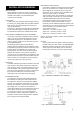
INSTALLATION GENERAL PIPE FITTINGS All pipe fittings are made via 22mm compression fittings directly to the unit. The fittings are threaded 3/4”BSP male parallel, should threaded pipe connections be required. COLD FEED A 22mm cold water supply is recommended, however, if a 15mm (1/2”) supply exists, which provides sufficient flow, this may be used (although more flow noise may be experienced).
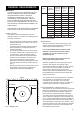
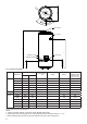
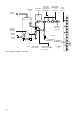
Ø5 595 50 45° 25° 30° 45° HOT OUTLET B A T&P VALVE 315 306 - direct COLD INLET 354 - indirect PRIMARY FLOW PRIMARY RETURN Fig. 4 General dimensions Type Indirect Direct Model Reference Dimensions (mm) Primary Flow (ltrs/min @80°C +/- 2°C) Coil Rating (kW) Heat-up Time (mins) Hot Water Capacity (ltrs) B 120zi 930 615 15 12.5 29 104 150zi 1114 800 15 12.5 37 138.5 170zi 1240 925 15 15 35 156.
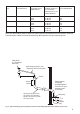
INSTALLATION DISCHARGE DISCHARGE PIPEWORK It is a requirement of Building Regulation G3 that any discharge from an unvented system is conveyed to where it is visible, but will not cause danger to persons in or about the building. The tundish and discharge pipes should be fitted in accordance with the requirements and guidance notes of Building Regulation G3. The G3 Requirements and Guidance section 3.50 - 3.63 are reproduced in the following sections of this manual.
3.
VALVE OUTLET SIZE MINIMUM SIZE OF DISCHARGE PIPE D1 MINIMUM SIZE OF DISCHARGE PIPE D2 FROM TUNDISH MAXIMUM RESISTANCE ALLOWED, EXPRESSED AS A LENGTH OF STRAIGHT PIPE (I.E. NO ELBOWS OR BENDS RESISTANCE CREATED BY EACH ELBOW OR BEND G 1/2 15MM G 3/4 22MM G1 28MM 22mm 28mm 35mm 28mm 35mm 42mm 35mm 42mm 54mm UP TO 9M UP TO 18M UP TO 27M UP TO 9M UP TO 18M UP TO 27M UP TO 9M UP TO 18M UP TO 27M 0.8M 1.0M 1.4M 1.0M 1.4M 1.7M 1.4M 1.7M 2.
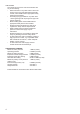
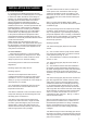
T&P RELIEF VALVE EXPANSION VESSEL BALANCED COLD WATER CONNECTION (IF REQUIRED) COLD WATER COMBINATION VALVE (2-PIECE) MAINS WATER SUPPLY TO HOT OUTLETS ISOLATING VALVE (NOT SUPPLIED) ELEMENT / CONTROLS HOUSING PRIMARY RETURN TUNDISH PRIMARY FLOW INLET Fig.
INSTALLATION - DIRECT SAFETY DISCONNECT FROM THE MAINS ELECTRICAL SUPPLY BEFORE REMOVING ANY COVERS. Never attempt to replace the immersion heater(s) other than with the recommended immersion heater(s). DO NOT BYPASS THE THERMAL CUT-OUT(S) IN ANY CIRCUMSTANCES. Ensure the two male spade terminations on the underside of the combined thermostat and thermal cut-out are pushed firmly onto the corresponding terminations on the element plate assembly.
INSTALLATION - INDIRECT SAFETY DISCONNECT FROM THE MAINS ELECTRICAL SUPPLY BEFORE REMOVING ANY COVERS. Never attempt to replace the immersion heater(s) other than with the recommended authorised immersion heater(s). DO NOT BYPASS THE THERMAL CUT-OUT(S) IN ANY CIRCUMSTANCES. Ensure the two male spade terminations on the underside of the combined thermostat and thermal cut-out are pushed firmly onto the corresponding terminations on the element plate assembly.
Fig. 9: Schematic wiring diagram - Basic 2 x 2 port valve system Fig. 10: Schematic wiring diagram - 3 port mid position valve system. N.B.
COMMISSIONING FILLING THE UNIT WITH WATER Ensure that all fittings and immersion heaters are correctly fitted and tightened. An immersion heater key is provided to aid tightening the immersion heater(s) • Check expansion vessel pre-charge pressure The vessel is supplied precharged to 0.35MPa (3.5 bar) to match the control pressure of the pressure reducing valve. The precharge pressure is checked using a car tyre gauge by unscrewing the plastic cap opposite the water connection.
MAINTENANCE MAINTENANCE REQUIREMENTS Unvented hot water systems have a continuing maintenance requirement in order to ensure safe working and optimum performance. It is essential that the relief valve(s) are periodically inspected and manually opened to ensure no blockage has occurred in the valves or discharge pipework. Similarly cleaning of the strainer element and replacement of the air in the expansion vessel will help to prevent possible operational faults.
USER INSTRUCTIONS WARNINGS IF WATER DISCHARGES FROM THE TEMPERATURE/PRESSURE RELIEF VALVE ON CYLINDER SHUT DOWN THE BOILER. DO NOT TURN OFF ANY WATER SUPPLY. CONTACT A COMPETENT INSTALLER FOR UNVENTED WATER HEATERS TO CHECK THE SYSTEM. DO NOT TAMPER WITH ANY OF THE SAFETY VALVES FITTED TO THE SYSTEM. IF A FAULT IS SUSPECTED CONTACT A COMPETENT INSTALLER.
FAULT FINDING & SERVICING IMPORTANT • After servicing, complete the relevant Service Interval Record section of the Benchmark Checklist located on page 22 and 23 of this document. • Servicing should only be carried out by competent persons in the installation and maintenance of unvented water heating systems. • Any spare parts used MUST be authorised parts. • Disconnect the electrical supply before removing any electrical equipment covers.
SPARES Item Description Number 14 Part Number 1 Immersion heater (Bent) 95 606 984 2 Immersion heater (Straight) 95 606 986 3 Solar pocket plate assembly 95 607 064 4 Blanking plate assembly 95 605 881 5 Immersion heater gasket 95 611 822 6 Immersion heater backnut 95 607 869 7 Immersion heater key spanner 95 607 861 8 Indirect thermostat & thermal cut-out 95 612 716 9 Direct thermostat & thermal cut-out 95 612 717 10 Solar thermal cut-out 95 612 698 11 6 Way terminal block
HEAT LOSS Nominal Capacity (Litres) ENVIRONMENTAL Standing Heat Loss per day (kWh/24h) per year (kWh/365d) 120 1.25 456.3 150 1.45 529.3 170 1.63 595.0 210 1.91 697.2 250 2.22 810.3 300 2.52 919.8 Products are manufactured from many recyclable materials. At the end of their useful life they should be disposed of at a Local Authority Recycling Centre in order to realise the full environmental benefits.
52.0 Standing loss in W 60.0 150.0 C 150zi 68.0 170.0 C 170zi 80.0 210.0 C 210zi 93.0 250.0 D 250zi 105.0 300.0 D 300zi 20.790 4478 37.4 D XL 395 250.0 250zd Table Direct: Technical parameters in accordance with European Commission regulations 814/2013 and 812/2013 See page 3 to 19 20.300 4395 38.1 C XL 332 210.0 210zd Specific precautions that shall be taken when the water heater is assembled, installed or maintained and disposed of at end of life 12.
NOTES 21
MAINS PRESSURE HOT WATER STORAGE SYSTEM COMMISSIONING CHECKLIST This Commissioning Checklist is to be completed in full by the competent person who commissioned the storage system as a means of demonstrating compliance with the appropriate Building Regulations and then handed to the customer to keep for future reference. Failure to install and commission this equipment to the manufacturer’s instructions may invalidate the warranty but does not affect statutory rights.
SERVICE RECORD It is recommended that your hot water system is serviced regularly and that the appropriate Service Record is completed. Service Provider Before completing the appropriate Service Record below, please ensure you have carried out the service as described in the manufacturer’s instructions.
Sales & Support Guarantee Servicing Spares On site service support including parts and labour for 12 months from date of installation. After the initial 12 months, a guarantee will apply for a further 24 years for the stainless steel inner vessel only. During this 24 year period, in the event of a cylinder leak, a replacement product will be issued provided that the replacement is carried out by one of our heateam engineers, for which reasonable labour charges will apply.