
Installation Instructions


12
SAFETY
DISCONNECT FROM THE MAINS ELECTRICAL
SUPPLY BEFORE REMOVING ANY COVERS.
Never attempt to replace the immersion heater(s)
other than with the recommended authorised
immersion heater(s).
DO NOT BYPASS THE THERMAL CUT-OUT(S)
IN ANY CIRCUMSTANCES. Ensure the two
male spade terminations on the underside of the
combined thermostat and thermal cut-out are
pushed rmly onto the corresponding terminations
on the element plate assembly.
In case of difculty contact service support; contact
details available at the back of this booklet.
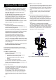
ELECTRICAL SUPPLY
All electrical wiring should be carried out by a
competent electrician and be in accordance with the
latest I.E.E Wiring Regulations.
Each circuit must be protected by a suitable fuse
and double pole isolating switch with a contact
separation of at least 3mm in both poles.
The immersion heater(s) should be wired in
accordance with Fig 8. The immersion heaters
MUST be earthed. The supply cable should be
1.5mm
2
3 core HOFR sheathed and must be routed
through the cable grip provided with the outer sheath
of the cable rmly secured by tightening the screws
on the cable grip.
DO NOT operate the immersion heaters until the
cylinder has been lled with water.
Ensure the thermostat and thermal cut-out sensing
bulbs are pushed fully into the pockets on the element
plate assembly.
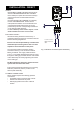
PLUMBING CONNECTIONS
Indirect cylinders require the following
pipework connections.
• Cold water supply to and from inlet controls.
• Outlet to hot water draw off points.
• Discharge pipework from valve outlets to
tundish.
• Connection to the primary circuit.
All connections are 22mm compression. However,
3/4”BSP parallel threaded ttings can be tted to the
primary coil connections if required.
BOILER SELECTION
The boiler should have a control thermostat and non
self-resetting thermal cut-out and be compatible with
unvented storage water heaters.
Where use of a boiler without a thermal cut-out
is unavoidable a “low head” open vented primary
circuit should be used. The feed and expansion
cistern head above the cylinder should not exceed
2.5m.
PRIMARY CIRCUIT CONTROL
The 2 port motorised valve supplied with the cylinder
MUST be tted on the primary ow to the cylinder
heat exchanger and wired in series with the indirect
control thermostat and thermal cut-out tted to the
unit.
Primary circulation to the cylinder heat exchanger
must be pumped; gravity circulation WILL NOT
WORK.
SPACE AND HEATING SYSTEMS CONTROLS
The controls provided with the cylinder will ensure
the safe operation of the unit within the central
heating system. Other controls will be necessary to
control the space heating requirements and times
that the system is required to function, see Fig. 8
below.
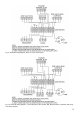
The cylinder is compatible with most heating
controls, examples of electrical circuits are shown in
Figs. 9 and 10 (Page 13). However, other systems
may be suitable, refer to the controls manufacturers’
instructions, supplied with the controls selected, for
alternative system wiring schemes.
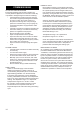
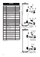
INSTALLATION - INDIRECT
L
N
1 2 3
Element Connections
1.5mm² 3 Core
HOFR sheathed
cable
Indirect control
wiring
Fig. 8: Electrical connections (indirect schematic)