
Installation Instructions


16
WARNINGS
IF WATER DISCHARGES FROM THE
TEMPERATURE/PRESSURE RELIEF VALVE ON
CYLINDER SHUT DOWN THE BOILER. DO NOT
TURN OFF ANY WATER SUPPLY. CONTACT
A COMPETENT INSTALLER FOR UNVENTED
WATER HEATERS TO CHECK THE SYSTEM.
DO NOT TAMPER WITH ANY OF THE SAFETY
VALVES FITTED TO THE SYSTEM. IF A FAULT
IS SUSPECTED CONTACT A COMPETENT
INSTALLER.
BENCHMARK
The cylinder is covered by the Benchmark Scheme
which aims to improve the standards of installation
and commissioning of domestic heating and
hot water systems in the UK and to encourage
regular servicing to optimise safety, efciency and
performance.
Benchmark is managed and promoted by the
Heating and Hotwater Industry Council. For more
information visit www.centralheating.co.uk.
Please ensure that the installer has fully completed
the Benchmark Checklist (Page 22 & 23) of this
manual and that you have signed it to say that
you have received a full and clear explanation of
its operation. The installer is legally required to
complete a commissioning checklist as a means of
complying with the appropriate Building Regulations
(England & Wales).
All installations must be notied to Local Area
Building Control either directly or through a
Competent Persons Scheme. A Building Regulations
Compliance Certicate will then be issued to the
customer who should, on receipt, write the
Notication Number on the Benchmark Checklist.
This product should be serviced regularly to optimise
its safety, efciency and performance. The service
engineer should complete the relevant Service
Record on the Benchmark Checklist after each
service.
The Benchmark Checklist may be required in the
event of any warranty work and as supporting
documentation relating to home improvements
in the optional documents section of the Home
Improvements Pack.
FLOW PERFORMANCE
When initially opening hot outlets a small surge in
ow may be noticed as pressures stabilise. This is
quite normal with unvented systems. In some areas
cloudiness may be noticed in the hot water. This is
due to aeration of the water, is quite normal and will
quickly clear.
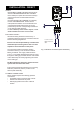
TEMPERATURE CONTROLS – DIRECT UNITS
IMMERSION HEATER(S)
A combined adjustable thermostat and thermal
cut-out is provided for each immersion heater. The
thermostat is factory set to give a water storage
temperature of approx. 55°C to 60°C. Access to the
thermostat can be made by opening the immersion
heater cover - DISCONNECT THE ELECTRICAL
SUPPLY BEFORE OPENING THE COVER(S).
Temperature adjustment is made by inserting a at
bladed screwdriver in the slot on the adjustment
disc on top of the thermostat and rotating. The
adjustment range 1 to 5 represents a temperature
range of 12°C to 68°C (60°C will be approximately
position 4). If in any doubt contact a competent
electrician.
DO NOT bypass the thermal cut-out(s) in any
circumstances.
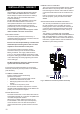
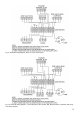
TEMPERATURE CONTROLS - INDIRECT UNITS
The cylinder units are tted with an indirect
thermostat and thermal cut-out. These controls must
be wired in series with the 2 port motorised zone
valve supplied to interrupt the ow of primary water
around the heat exchanger coil when the control
temperature has been reached. The controls are
located within the lower terminal housing along with
the immersion heater thermostat. The thermostat
is factory set to give a water storage temperature
of approx. 55°C to 60°C. Access to the thermostat
can be made by opening the terminal housing
cover - DISCONNECT THE ELECTRICAL SUPPLY
BEFORE OPENING THE COVER. Temperature
adjustment is made by inserting a at bladed
screwdriver in the adjustment knob and rotating. The
minimum thermostat setting is 12°C. The adjustment
range 1 to 5 represents a temperature range of 12°C
to 68°C (60°C will be approximately position 4). If in
any doubt contact a competent electrician.
An immersion heater is also provided for use should
the indirect heat source be shut down for any purpose.
The immersion heater control temperature is set
using the immersion heater thermostat.
DO NOT bypass the thermal cut-out(s) in any
circumstances.
OPERATIONAL FAULTS
Operational faults and their possible causes are
detailed in the Fault Finding section of this book. It
is recommended that faults should be checked by a
competent installer.
The air volume within the expansion vessel will
periodically require recharging to ensure expanded
water is accommodated within the unit. A discharge
of water INTERMITTENTLY from the expansion
valve will indicate the air volume has reduced to
a point where it can no longer accommodate the
expansion.
USER INSTRUCTIONS