
Installation Instructions


3
IMPORTANT:
THIS APPLIANCE IS NOT INTENDED FOR THE
USE BY PERSONS (INCLUDING CHILDREN)
WITH REDUCED PHYSICAL, SENSORY
OR MENTAL CAPABILITIES, OR LACK OF
KNOWLEDGE AND EXPERIENCE, UNLESS
THEY HAVE BEEN GIVEN SUPERVISION OR
INSTRUCTION CONCERNING THE USE OF THE
APPLIANCE BY A PERSON RESPONSIBLE FOR
THEIR SAFETY.
CHILDREN MUST BE SUPERVISED TO ENSURE
THEY DO NOT PLAY WITH THE APPLIANCE.
SITING THE UNIT
The cylinder must be vertically oor mounted.
Although location is not critical, the following points
should be considered:
• The cylinder should be sited to ensure minimum
dead leg distances, particularly to the point of
most frequent use.
• Avoid siting where extreme cold temperatures
will be experienced. All exposed pipe work
should be insulated.
• The discharge pipework from the safety valves
must have minimum fall of 1:200 from the unit
and terminate in a safe and visible position.
• Access to associated controls and immersion
heaters must be available to provide for the
servicing and maintenance of the system.
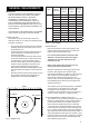
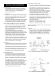
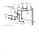
Where these controls are installed against a wall a
minimum distance of 250mm must be left (see
Fig. 1).
• Ensure that the oor area for the cylinder is level
and capable of permanently supporting the
weight when full of water. (see Table 1)
WATER SUPPLY
Bear in mind that the mains water supply to the
property will be supplying both the hot and cold
water requirements simultaneously.
It is recommended that the maximum water
demand is assessed and the water supply
checked to ensure this demand can be
satisfactorily met.
Note: A high mains water pressure will not
always guarantee high ow rates.
Wherever possible the mains supply pipe should
be 22mm. We suggest the minimum supply
requirements should be 0.15MPa (1.5 bar) pressure
and 20 litres per minute owrate. However, at
these values outlet ow rates may be poor if
several outlets are used simultaneously. The higher
the available pressure and ow rate the better the
system performance.
The cylinder has an operating pressure of 0.35MPa
(3.5 bar) which is controlled by the cold water
combination valve assembly. The cold water
combination valve assembly can be connected to a
maximum mains pressure of 1.6MPa (16 bar).
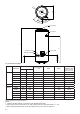
OUTLET/TERMINAL FITTINGS (TAPS, ETC.)
The cylinder can be used with most types of terminal
ttings. It is advantageous in many mixer showers
to have balanced hot and cold water supplies. In
these instances a balanced pressure cold water
connection should be placed between the 2 pieces
of the cold water combination valve assembly (see
Fig. 2). Outlets situated higher than the cylinder will
give outlet pressures lower than that at the heater, a
10m height difference will result in a 0.1MPa (1 bar)
pressure reduction at the outlet. All ttings, pipework
and connections must have a rated pressure of at
least 0.6MPa (6 bar) at 80°C.
GENERAL REQUIREMENTS
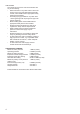
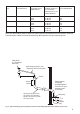
Table 1: Unit weights
Fig. 1: Siting the Unit
WALL
Min 250mm
Min 250mm
Type
Model
Reference
Nominal
Capacity
(litres)
Weight of
unit full
(Kg)
Weight
of unit
(Kg)
Indirect 120zi 120 147 27
150zi 150 182 32
170zi 170 204 34
210zi 210 250 40
250zi 250 294 44
300zi 300 352 52
Direct 120zd 120 144 24
150zd 150 178 28
170zd 170 201 31
210zd 210 247 37
250zd 250 289 39
300zd 300 349 49