
User's Manual
Litenode™ wireless node
3
Antenna location and installation
The antenna for the model ELIR1 Lightnode relay is integral to the unit and is contained wholly within the
device itself. It is not accessible to the user and may not be modified in any way.
To satisfy FCC RF exposure requirements for mobile transmitting devices, a separation of 20 cm or
more should be maintained between the antenna of this device and persons during device operation.
To ensure compliance, operations at closer distance than 20 cm is not recommended.
Troubleshooting
General
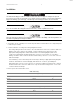
• Make sure the wires are connected according to the wiring diagram.
• Make sure the wires have proper contact and are securely connected.
• If no LEDs are lit, then check the power.
Lights won’t turn on when relay is being powered:
• Make sure the wires are properly connected.
• Make sure the yellow LED is blinking.
Light won’t turn off after command has been sent:
• Make sure that relay is receiving communication (red LED blinks)
Relay doesn’t respond to commands:
• Make sure no obstacle (concrete, metal, etc.) is present between relay antenna and the emitter.
LED indicators:
• Yellow: blinks every 3 seconds to indicate that relay is powered and functioning normally
• Red: flashes to indicate message reception
• Green: flashes to indicate message transmission by the relay.
If there is no message reception/transmission, then possible causes are antenna positioning and
distance from another relay or the gateway.
Specifications
• Model: ELIR1
• IC: 4557A-ELIR1
• FCC ID: QZC-ELIR1
• Operating range: 110 VAC to 480 VAC 50 Hz or 60 Hz
• Maxoutput:8A(2Aat480V)
• Inputs: 1 digital (0 VDC to 30 VDC), optional
• Output: 24 VDC 50 mA max
• Continuous retroactive0Vto10Vdimming
See the product data sheet for complete details
DRAFT