
User's Manual


IL42-4020C September 2007
2
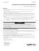
Figure 1. Retaining clip and connector lead
Local External Antenna
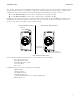
If the A3 ALPHA meter is used in a metal service cabinet, using a local external antenna may be necessary. To obtain
better coverage, the local external antenna can be mounted on the top of the metal service cabinet or the meter
socket enclosure (see [1] in Figure 2).
Elster recommends Antenex Inc.’s 902-928 MHz Permanent Mount antenna (TRAB9023P).
1
To mount the antenna on
the service cabinet or meter socket enclosure, drill a 5/8-inch hole into the cabinet wall with a step drill. Insert the
antenna through the hole. After the antenna is mounted, the antenna’s Type N female connector can be mated with the
meter’s Type N male connector.
For installations where the mounting for the local antenna does not provide a conductive metallic ground plane, the
Antenex TRAB9023NP (no ground plane required) may be employed. The gain and pattern are virtually identical with
the TRAB9023P version and the TRAB9023NP may also be employed on metallic ground planes with good results.
Remote External Antenna
If the A3 ALPHA meter is used in a metal building, or the meter is installed in a location where the site requires an
antenna at a greater height to overcome blocked signals, a remote antenna may be required. If a remote external
antenna is used, a lightning/surge arrestor should be installed at the bottom of the socket enclosure (see [2] in
Figure 2). Elster recommends a PolyPhaser DSXL IN-LINE EMP surge filter (Tessco P/N 491574).
2
NOTICE
Do not use a standard RG-8/U cable with solid polyethylene dielectric. The losses in solid dielectric RG-8/U cables in
short distances make solid dielectric RG-8/U cables unacceptable.
The most economical connection to the remote external antenna is the RG-8/U “foam” or “LMR-400” type cable. This
type of cable should be suitable for distances of up to 100 feet. The foam dielectric cable will incur a loss of
approximately 3.9 dB in 100 feet (or approximately 2 dB in 50 feet). The coaxial cable should be mounted at the
bottom of the meter socket in “drip loop” fashion. A “drip loop” is formed by bringing the coaxial cable to a point below
the meter socket and then bending it back up to the connector. This forms a U-shape, which allows water to run down
the cable exterior. Antenna cables should be ordered with N-type male connectors on each end.
1
Antenex, 2000-205 Bloomingdale Road, Glendale Heights IL 60131. Telephone: 630-351-9007. Website: antenex.com
2
PolyPhaser Corporation, 2225 Park Place, Minden, NV 89423. Telephone: 800-325-7170.
Website: polyphaser.com.
N-type connector
to external antenna
Connector lead
External antenna
connection lead
Wire tie
Retaining clip