
Specifications


Chapter 3 – Input/Output Interfaces
98 PL 3120/PL 3150/PL 3170 Power Line Smart Transceiver Data Boo
k
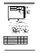
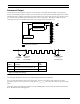
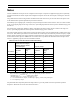
Pulsecount Output
A timer/counter can be configured to generate a series of pulses. The number of pulses output is in the range 0 to
65,535, and the output waveform is a square wave of 50% duty cycle. This function suspends application processing
until the pulse train is complete. The frequency of the waveform can be one of eight values given by Table 3.9 in the
Notes section at the end of this chapter with clock select values of 0 through 7. This object is useful for external
counting devices that can accumulate pulse trains, such as stepper motors (see Figure 3.53).
RETURN FROM
io_out()
FUNCTION CALL
t
ret
t
fout
1ST ACTIVE
OUTPUT
PULSE EDGE
io_out()
FUNCTION
CALL
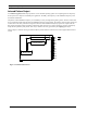
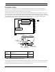
System Clock
Divide Chain
Timer/Counter 1
Timer/Counter 2
IO10
IO9
IO8
IO0
IO1
IO2
IO3
IO4
IO5
IO6
IO7
High Current Sink Drivers
IO11
Symbol Description
Typ @
10MHz
t
fout
Function call to first active output pulse edge 115 µs
t
ret
Return from function 5 µs
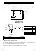
Figure 3.53 Pulsecount Output
The return from this function does not occur until all output pulses have been produced.
t
fout
is the time from function call to first output pulse. Therefore, the calling of this function ties up the
application processor for a period of N x (pulse period) + t
fout
+ t
ret
, where N is the number of specified output
pulses.
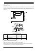
The polarity of the output depends on whether or not the invert option was used in the declaration of the function
block. The default is low with high pulses.