
Specifications
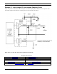


Chapter 4 – Coupling Circuits
130 PL 3120/PL 3150/PL 3170 Power Line Smart Transceiver Data Boo
k
Coupling Circuit Tutorial
Power Line Communications Background
The PL Smart Transceivers employ sophisticated digital signal processing techniques, a transmit power amplifier with a
very low output impedance, and a very wide (>80dB) dynamic range receiver to overcome the signal attenuation and
noise inherent in power mains communication. Maintaining the full communication capability of the PL Smart
Transceivers requires careful selection and implementation of the mains coupling circuitry associated with those
transceivers. This section gives an overview of the sources of signal attenuation as a basis for understanding choices in
selecting and implementing mains coupling circuits.
Attenuation is the difference between the signal level at the output of the power line transmitter and the level of that
same signal at the input of the intended receiver. While attenuation is often defined as the ratio of power levels, it is
referred to in this document as the ratio of the transmitted signal voltage (unloaded) to the voltage of that same signal at
the receiver input. A voltage ratio is more convenient to measure because power measurements require knowledge of the
circuit impedance which, in the case of the power mains, varies with both location and time.
In power mains communications the attenuation of transmitted signals spans a wide range and is most conveniently
denoted in decibels (dB), where voltage attenuation is defined in dB as 20log
10
(V
transmit
/V
receive
). Thus 20dB of attenuation
means that the signal was reduced by a factor of 10 by the time it arrived at the receiver, 40dB of attenuation corresponds
to a factor of 100, 60dB a factor of 1000, and so on. A PL Smart Transceiver is capable of reliably communicating on a
low-noise line, such as a dedicated twisted wire pair, when the transmit signal is attenuated by 80dB (a factor of 10,000).
Thus a signal transmitted at 7Vp-p (2.5V
RMS
) can be received when reduced to less than 700µVp-p (250µV
RMS
).
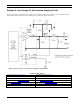
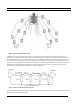
To better understand the sources of attenuation in a network of power mains, it is helpful to look at a simplified model of
a power distribution network. This example is based on an installation having one power distribution panel and two
phases of mains power. While many applications for power line communication employ different numbers of phases,
different topologies, voltages, and wire types, this example illustrates some of the key issues affecting the successful
application of the PL Smart Transceiver.
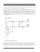
Figure 4.12 depicts the path that a power line communication signal might traverse, starting from a wall socket and
passing through the building's electrical wiring and circuit breaker panel, across power phases, and ultimately to another
wall socket. Each socket in the power network can power a device that generates noise and loads the communications
signal. For clarity, neutral and earth wires have not been shown.