
Specifications

PL 3120/PL 3150/PL 3170 Power Line Smart Transceiver Data Book 139
In instances where large ambient magnetic fields might be present (such as from switched mode power supply open
frame magnetic elements), it is possible that one or more of the PL Smart Transceiver coupling circuit inductors might
pick up these stray fields and conduct them onto the power mains. Depending on the frequency and amplitude of these
fields they could result in failure to meet conducted emission regulations.
If noise from parasitic coupling is suspected, it can be confirmed by inserting a 10cm (4 inch) twisted wire pair in series
with one of the inductors in question. If the conducted noise spectrum varies by more than a few dB when this inductor is
moved closer to, and farther from, other components, then parasitic coupling might be the source of the problem.
If stray coupling is a problem, regulations can usually be met by adjusting the location or orientation of the radiating
device relative to the coupling circuit inductors. Alternately, shielded or toroidal inductors can be used to reduce
coupling as long as all electrical parameters specified in the example coupling circuit tables given later in this chapter are
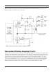
met. If, however, a toroidal or shielded inductor is used in place of L102, then the selected part must handle the
maximum output current of the PL Smart Transceiver transmit amplifier without approaching saturation. If L102 even
approaches saturation it can add harmonics of the PL Smart Transceiver transmit signal which might result in failure to
meet conducted emission regulations (in this instance, due to inductor distortion instead of a stray pickup). For this
reason, a shielded or toroidal inductor used for L102 should have DC current rating two or three times higher than listed
in the example circuits given later in this chapter. The recommended open frame axial inductors do not need this extra
operating margin due to the linearity provided by a magnetic path that is partly in air.
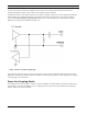
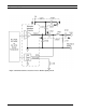
Coupling Circuit Receive Impedance
To avoid attenuating receive signals, the transmit amplifier of the PL Smart Transceiver is switched to a high impedance
state (approximately 500 ohms) when it is not transmitting. The receive-mode impedance of the PL Smart Transceiver
circuitry, in conjunction with the coupling circuits recommended in this chapter, is greater than 250 ohms in the
communication frequency range (70kHz to 90kHz for A-band and 110kHz to 138kHz for C-band).
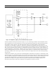
Regulations in some countries might set a limit on how low the receive-mode impedance can be outside the
communication frequency range. The receive-mode impedance of most coupling circuits dips near 10kHz due to a series
resonant effect between the line coupling capacitor (C101) and the coupling inductor (L101). This dip in receive-mode
impedance near 10kHz does not have any adverse effect on the communication performance of the PL Smart
Transceivers. If local regulations require a minimum out of band receive impedance of 5 ohms, then this can be
accomplished by selecting an inductor, L1, which has more than 5 ohms of DC resistance. In order to meet conducted
emission regulations, the DC resistance of this inductor should not exceed 14 ohms, as specified in the example coupling
circuits shown in this chapter.
Safety Issues
This guide is intended only as an introduction to some of the safety issues associated with designing circuits using the PL
Smart Transceiver. This document is not a primer on electrical safety or electrical codes, and it is the responsibility of the
user to become familiar with any applicable safety rules or regulations. A review of all designs by competent safety
consultants and the pertinent regulatory or safety agencies is strongly recommended.
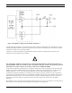
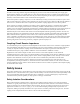
Safety Isolation Considerations
Many products include an isolation barrier in the form of an insulated enclosure between a user and any hazardous
conductors. A typical product of this type is a light switch in which the PL Smart Transceiver and all of the associated
electrical components are contained inside the switch enclosure. The type of coupling circuit that can be used in these
applications is called a non-isolated coupling circuit. A non-isolated coupling circuit generally requires lower cost
components, making it especially desirable for use in price-sensitive consumer products and wiring devices. All of the
coupling circuit examples that have been shown so far are of the non-isolated type.