
Specifications

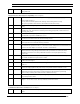

Appendix B –PL Smart Transceiver-Based Device Checklist
228 PL 3120/PL 3150/PL 3170 Power Line Smart Transceiver Data Boo
k
41
The signal return traces from the AC mains connection to the transmit amplifier are a copper plane or
≥1.3mm wide and ≤15cm long (before becoming a ground plane).
42
Traces from the point where D101 taps into the signal path to the point where C103 connects back to
ground are ≥1.3mm wide and ≤2cm long.
43
The traces between the V
A
input of the transmit amplifier and the point where C103 connects back to
ground are at least 1.3mm wide and no more than 4cm long.
44
Surge testing has been performed in accordance with applicable surge standards and the application
requirements.
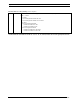
Power Supply (refer to Chapter 5)
45
Type of V
A
power supply (from Table 5.4, or if some other type is used provide a text description):
_________________________________________________________________________________
Type of V
DD5
power supply:
_____________________________________________ ___________________________________
If traditional linear supplies are used for both V
A
and V
DD5
, then skip check list items 46, 47, and 49 -
55. If either supply contains switching elements, then complete this section in its entirety.
46
If a the selected power supply is one of the “Pre-Verified” type from Table 5.4, then check that it
matches the documentation for that supply in Chapter 5 - noting any deviations.
47
If the selected reference design uses a 1Ap-p transmit amplifier, verify that the V
A
power supply
operates in the range of 8.5V to 18.0V during receive mode and 10.8V to 18.0V during transmit mode
(refer to Chapter 5).
48
If the selected reference design uses a 2Ap-p transmit amplifier, verify that the V
A
power supply
operates in the range of 12.0V to 18.0V during receive mode, 14.25V to 18.0V for C-band transmit
mode and 12.0V to 18.0V for A-band transmit mode (refer to Chapter 5).
49 *
Switching supplies operate in the recommended frequency ranges of 46kHz - 55kHz, or 90kHz -
110kHz, or >155kHz under all line, load, environmental, and volume production variations.
50
A series inductor is used between the power supply input and the power mains to avoid attenuation due
to the input stage of a switching power supply.
51
The value of the series inductor has been selected according to the application requirements of Table
5.9.
52
The series power supply inductor has a current rating adequate to support the peak currents drawn by the
power supply without saturation.
53
The resonant frequency of the LC circuit created by the inductor and the input capacitance of the
switching supply is at least 1 octave from the communication frequency range (70kHz-90kHz for A-
band and 110kHz-138kHz for C-band).
54
The power supply complies with the input noise masks shown in Chapter 5.
Measurement of the power supply was made by connecting the supply to the artificial mains network as
specified in sub clause 8.2.1 of CISPR Publication 16. Measurements are made over the full range of
anticipated loads on the supply and conducted in accordance with the CENELEC EN 50065-1 or FCC
measurement standards with measurement bandwidths of 200Hz below 150kHz and 9kHz above
150kHz, as described in CISPR Publication 16.
55
If the power supply does not meet the appropriate noise mask, an appropriate filter is installed between
the local switching power supply and the power line (refer to Chapter 5).