
Specifications

PL 3120/PL 3150/ PL 3170 Power Line Smart Transceiver Data Book 43
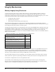
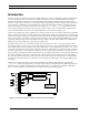
Parallel I/O
TIMER/COUNTER
INPUT
OBJECTS
TIMER/
COUNTER
OUTPUT
OBJECTS
SERIAL
I/O
OBJECTS
PARALLEL
I/O
OBJECTS
DIRECT
I/O
OBJECTS
Bit Input, Bit Output
Byte Input, Byte Output
Leveldetect Input
Nibble Input, Nibble Output
I/O Pin
Muxbus I/O
Master/Slave A
Slave B
Bitshift Input, Bitshift Output
I
2
C I/O
Magcard Input
Magtrack1 Input
Master
Slave
Serial Input
Serial Output
Wiegand Input
Edgedivide Output
Frequency Output
Oneshot Output
Pulsecount Output
Pulsewidth Output
Triac Output
Triggeredcount Output
High Sink
Pull Ups
Standard
Dualslope Input
Edgelog Input
Infrared Input
Ontime Input
Period Input
Pulsecount Input
Quadrature Input
Totalcount Input
Control
Neurowire I/O
CDCD C
D
CD
CD
C
CD
Control
01 2 3 4 5 6 7 8 910
Control
CD
Optional Timeout
D
CD
Optional Chip Select
D
CDOptional Timeout
CDOptional Timeout
Any Two Pins (Optional Timeout)
012345678910
All Pins 0 – 7
4 + 5 6 + 7
Sync Input
Data Pins 0 – 7
ALS WS RS
Any Four Adjacent Pins
Data Pins 0 – 7
A0
CS R/W
Data Pins 0 – 7
CS R/W HS
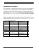
Notes:
C = Clock, D = Data
Bitshift, I
2
C, Magcard, Magtrack,
Neurowire
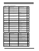
Timer/Counter 1 Devices
One of:
IO_6 input quadrature
IO_4 input edgelog
IO_0 output [triac | triggeredcount |
edgedivide] sync(IO_4..7)
IO_0 output [frequency |
infrared_pattern | oneshot |
pulsecount | pulsewidth]
Or up to four of:
IO_4 input [ontime | period ⎟
pulsecount⎟ totalcount ⎟
dualslope⎟ infrared] mux
IO_5..7 input [ontime | period ⎟
pulsecount⎟ totalcount ⎟
dualslope⎟ infrared]
Timer/Counter 2 Devices
One of:
IO_4 input quadrature
IO_4 input edgelog
IO_1 output [triac ⎟ triggeredcount ⎟
edgedivide] sync(IO_4)
IO_1 output [frequency⎟
infrared_pattern⎟ oneshot ⎟
pulsecount⎟ pulsewidth]
IO_4 input [ontime ⎟ period ⎟
pulsecount⎟ totalcount ⎟
dualslope⎟ infrared] ded
Sync Input
Sync Input
11
11
Pull Up
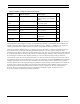
SCI (UART)
SPI
CD
Magcard Bitstream
CD
Optional Timeout
Touch I/O
Infrared Pattern Output
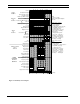
Figure 3.3 Summary of I/O Objects