Instruction Manual AVR-320 AV-Receiver
CONTENTS IMPORTANT SAFETY INSTRUCTIONS...................................................................................................................................................... 3 BEFORE USE .............................................................................................................................................................................................. 5 CONNECTION ..........................................................................................................
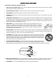
IMPORTANT SAFETY INSTRUCTIONS CAUTION: READ THIS BEFORE OPERATING YOUR UNIT. 1. READ AND FOLLOW INSTRUCTIONS: All the safety and operation instructions should be read before the product is operated. Follow all operation instructions within this manual. 2. RETAIN THESE INSTRUCTIONS: The safety and operation instructions should be retained for future reference. 3. HEED WARNINGS: Comply with all warnings on the product and in the operation instructions. 4.
IMPORTANT SAFETY INSTRUCTIONS 12. CONDITIONS REQUIREING SERVICE: Unplug this product from the wall outlet and refer servicing to qualified service personnel under the following conditions: a) If the unit exhibits sudden unusual operation or unusual display characteristics. b) If liquid has been spilled, or objects have fallen into the product. c) If the product has been exposed to rain or water.
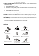
BEFORE USE Speaker Connections Caution: - To avoid damaging the speakers with a sudden high-level signal, be sure to switch the power off before connecting the speakers. - Check the impedance of your speakers. Connect speaker with an impedance of 6 ohms or more. - The amplifier’s colored speaker terminals are the + (positive) terminals and the black terminals are the – (negative) terminals. - The + side of the speaker cable is marked to make it distinguishable from the – side of the cable.
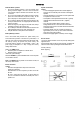
CONNECTION AM INDOOR LOOP ANTENNA - To stand the antenna on a flat surface, fix the claw to the slot. FM INDOOR ANTENNA If you live reasonably close to a transmitter and want to use the provided lead-type FM antenna, you will have to connect it direct to the “FM 75” socket. Fit the metal sleeve of the lead-type antenna over the core (center) conductor of the (FM 75) socket, extend the lead and fix it to a window frame or wall with thumbtacks, or the like, where reception is best.
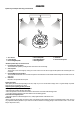
CONNECTION Speaker layout example when using surround mode 1 2 3 4 6 5 7 8 1. TV or Screen 4. Center Speaker 7. Surround Right Speaker 2. Front Left Speaker 5. Front Right Speaker 8. Listening Position 3. Subwoofer 6. Surround Left Speaker Standard speaker setup for surround sound ● Front Right and Left speakers These are the main speakers providing the front stereo effect of the sound image.
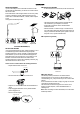
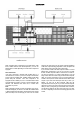
CONNECTION SPEAKER CONNECTION Power cord (AC) - Be sure to connect the power cord to an AC outlet, which supplies the correct voltage. - Hold the power plug when plugging or unplugging the power cord. Subwoofer Out Use this jack to connect an active subwoofer.
CONNECTION using just one video input on the TV (S-Video or RCA). Regardless of the video component being played DVD or VCR, the picture will always appear on the same video input of the monitor. If you use both S-Video and RCA composite cables to connect different video components to your unit, you must also use both S-Video and RCA composite cables to connect the TV monitor to your unit.
CONNECTION CD, TAPE jacks Connect the component with RCA to RCA cords. Make sure to connect: Audio connections: Some video components are equipped with special digital audio outputs (e.g. DVD players). If your video component is equipped with a digital audio output, it is recommended that you connect to your unit using a digital cable. Digital audio cables are required to use the DTS and Dolby Digital surround sound modes.
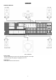
FRONT PANEL INFORMATION 1. POWER 2. STEREO 12. AUX 13. TUNER/BAND Press this button to select AUX. Press this button to select the TUNER. Press again to select FM and AM. 14. VIDEO 2 Press this button to select VIDEO 2. 15. VIDEO 1 Press this button to select VIDEO 1. 16. DVD Press this button to select DVD. To decrease or increase the Master Volume. 17. DTS/DOLBY DIGITAL 7. VFD DISPLAY UNIT Informs you of selected inputs and system state. 18. 2CH 8. PHONES Jack for stereo headphones. 19.
REAR PANEL INFORMATION 1. AC CORD: Connect to the AC mains socket. 2. SPEAKERS: External speakers power output. (Refer to Speaker Connection section) 3. SUB LINE OUT: Pre-out for an active subwoofer. 4. S-VIDEO IN/OUT terminals: - DVD S-VIDEO IN: Connect an S-VIDEO cable to the S-VIDEO output terminal of a DVD player. - VIDEO-S IN: For connection of S-VIDEO cable to the output terminal of an external player. - VIDEO-S OUT: For connection of S-VIDEO cable to the input terminal of an external player. 5.
REMOTE CONTROL UNIT BATTERY INSTALLATION REMOTE CONTROL By using the provided remote control unit, this unit can be controlled from your listening position. To use the remote control unit, point it at the REMOTE SENSOR window of this unit. Notes: - Even if the remote control unit is operated within the effective range, remote control operation may be impossible if there are any obstacles between the unit and the remote control.
REMOTE CONTROL INFORMATION 14
REMOTE CONTROL INFORMATION 1. 2. 3. 4. 5. 6. 7. 8. 9. 10. 11. 12. 13. 14. 15. 16. 17. 18. 19. 20. 21. 22. 23. 24. 25. 26. Power Push this button to turn the unit into standby mode, push it again to turn off the unit. Mute Press this button to mute the sound, push again to cancel the mute function. Input Mode Select Coaxial, Optical or Analog Input mode in DVD, AV1 and AV2. Dimmer Press this button to set the brightness of the front panel display.
BASIC OPERATION BASIC OPERATION 1 1. 2. 3. 4. Press the POWER button to put this unit into Standby Mode. Press one of the source buttons to activate the unit. Select the desired source by pressing DVD, VIDEO 1, VIDEO 2, TUNER, AUX or TAPE.
BASIC OPERATION PLAYING VIDEO SOURCES 1. Select DVD, VIDEO1, VIDEO 2 by pressing the corresponding button. 2. Play the sound source corresponding to the source selected (for example, if you have selected DVD, press PLAY on your DVD player). 3. The picture from the video source will be transmitted to the TV and the sound from the video source will be heard from the speakers. THE RADIO OPERATIONS Automatic Tuning 1. Press the POWER button, then press the TUNER button to turn ON this unit. 2.
BASIC OPERATION RADIO DATA SYSTEM (RDS) RDS is a method for the transmission of additional information from local radio stations (the system only operates for radio stations broadcasting in FM). Using RDS data you can see the name of the radio station, the name of the program and/or the type of program, all shown on the multi-function display (Note: RDS only functions when the local radio station includes the RDS transmission within its signal and when the signal is strong enough).
SPEAKER CONFIGURATION, DELAY TIME & DYNAMIC RANGE CONTROL SPEAKER CONFIGURATION It is important to configure your speakers correctly in order to get the most from your AV Receiver. This versatile AV Receiver provides the flexibility to experience multi-channel surround sound without a center speaker. However, for best results with Dolby Pro Logic II, DTS and Dolby Digital decoding, at least 5 speakers (Left, Center, Right, Left Rear and Right Rear) should be used.
TEST TONE, LFE TRIMMER & CHANNEL SELECT TEST TONE Speaker Level balance Adjustment The test tone function is useful to adjust the relative volume between speakers in DOLBY DIGITAL or DOLBY PRO LOGIC II mode. Once the balance is set, you don’t have to change the balance as long as the speakers aren’t moved. 1. Adjust the MASTER VOLUME to the normal listening level. (Half of max. Volume is recommended) 2. Press the TEST TONE button (on the remote control) in DTS, Dolby Digital or Dolby PRO LOGIC II mode.
AVAILABLE SURROUND MODE DOLBY DIGITAL MODE SURROUND MODE The surround modes create a “live” atmosphere such as that experienced in movie theaters, discos, stadiums and concert halls. Select the appropriate surround mode according to the program source. (Note: Surround speakers are needed for DTS/DOLBY DIGITAL Dolby Pro Logic II surround modes to function). It is recommended to use a Center speaker when operating this unit in DTS/DOLBY DIGITAL/Dolby Pro Logic II surround modes.
TROUBLESHOOTING To determine a problem with your AV Receiver, always check the most obvious possible causes first. If a problem still exists after having checked the possible causes below, consult your nearest dealer. Problem Amplifier When listening to the music in stereo, Left/Right speakers are reversed. Low hum or buzzing sound Sound is only heard from one channel Sound cuts off when listening to the music or no sound even though power is ON. Low bass response.
SPECIFICATIONS AUDIO SECTION Rated Power Output FRONT CENTER REAR Output Terminals FRONT CENTER REAR Total Harmonic Distortion Less than 0.05% at1/2 rated power output 50W + 50W 50W 50W + 50W 4 - 8 ohms 4 - 8 ohms 4 - 8 ohms LINE INPUT Input Sensitivity/Impedance Frequency Response Tone Control Range Signal-Noise Ratio 150mV/47kΩ 20Hz~20KHz +0.
For further information please visit our website: www.eltax.com Itemno.