CHAPTER 5 REPLACEMENT PROCEDURES 5.1 REQUIRED TOOLS 3M Products recommends the following tools as potential additions to those on hand at a repair facility. These items outfit the facility for the maintenance and repair of 3M Max Secure Printer Modules: TOOL KIT Item No. 5-2 Description 1 25 inch-pound Torque Screwdriver 2 15 inch-pound Torque Screwdriver 3 9 inch-pound Torque Screwdriver 4 5.5 inch-pound Torque Screwdriver 5 4 inch-pound Torque Screwdriver 6 2.
CHAPTER 5 REPLACEMENT PROCEDURES 5.2 PART REPLACEMENTS The following sections describe the requirements for removing both major assemblies and, where applicable, components on those assemblies that appear in the list of spares. Only removal descriptions appear. Unless noted otherwise, replacements can take place by reversing the steps required for removals. Also, replacements for some items in the spares list do not appear. These items are considered too easily identifiable to warrant descriptions. 5.2.
CHAPTER 5 REPLACEMENT PROCEDURES 5.2.2 White Card Feeder Station Removal Refer to Figure 5-2, and proceed as follows Step 1. Swing down the Front Panel and remove the, Rear, and Right Side Panels (see Section 5.2.1). Step 2. To replace the complete unit, unplug J3, J5 and the upper part of J17 on the Extension Board, and cut all related cable ties leading to the White Card Feeder Station. Step 3. Remove the four screws holding the unit to the Rear Plate.
CHAPTER 5 REPLACEMENT PROCEDURES 5.2.3 White Card Feeder Station Replacements Figure 5-3 shows the White Card Feeder Station. The timing belt, associated drive motor, and rollers are considered replaceable. After replacing the timing belt, adjust belt tension as follows: Step 1. Loosen the two screws holding the Idler Pulley bracket. Step 2. Swing the Idler Pulley against the timing belt to remove slack in the belt. Only remove belt slack. Do not stretch the belt. Step 3.
CHAPTER 5 REPLACEMENT PROCEDURES 5.2.4 Upper Clear Card Station Removal Figure 5-4 shows the fasteners holding the Upper Clear Card Station, the connections on the Expansion board, and the timing belt that extends card drive to the lower unit. To remove the unit, proceed as follows: Step 1. Remove the rear and right side case parts (see Section 5.3.1) and the Card Feeder Assembly (see Section 5.2.2). Step 2. Unplug the Shear, Stepper, and Clear Material Sensor connectors. Cut associated cable ties. Step 3.
CHAPTER 5 REPLACEMENT PROCEDURES 5.2.5 Upper Clear Card Station Component Replacements The Upper Clear Card Station includes a stepper motor, a related timing belt (that extends card drive to the lower unit), a Clear Material sensor, and the Clear Card Shear. Service personnel can replace any of these components and the Card Feed roller. The Clear Card Shear has a useful life in excess of 100,000 cuts. Figure 5-5 shows the fasteners for these components. Figure 5-5.
CHAPTER 5 REPLACEMENT PROCEDURES 5.2.6 Lower Clear Card Station Removal Refer to Figure 5-6, and proceed as follows: Step 1. Remove the Upper Clear Card Station (see Section 5.2.4). Step 2. Remove White Card Feeder Station sufficiently to gain clearance from the Lower Clear Card Station (see Section 5.2.2). Step 3. Remove connectors on the Clear Card Controller board that connect to the Lower Clear Card Station and J17 on the CPU Extension board (see Figure 5-26). Step 4.
CHAPTER 5 REPLACEMENT PROCEDURES 5.2.7 Lower Clear Card Station Components Figure 5-7 shows the components that comprise the Lower Clear Card Station. Figure 5-7. Lower Clear Card Station Components. 980286-001 Rev.
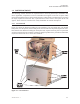
CHAPTER 5 REPLACEMENT PROCEDURES 5.2.8 Card Assembly Station Removal Refer to Figure 5-8, and proceed as follows: Step 1. Remove the rear and left side case members (see Section 5.2.1). Step 2. Unplug J19 from the Extension board. Step 3. Cut the ties holding the J19 cable to the chassis. Step 4. Remove the four fasteners holding the Card Assembly Station. Step 5. Feed the Card Assembly Station cables through the hole in the rear plate, and remove the station.
CHAPTER 5 REPLACEMENT PROCEDURES 5.2.9 Card Assembly Station Component Replacements Six components on the Card Assembly Station are considered replaceable—two sensors, a dc motor, a timing belt, a solenoid, and the Card Feed roller. Figure 5-9 shows these components. Figure 5-9. Card Assembly Station Components. 980286-001 Rev.
CHAPTER 5 REPLACEMENT PROCEDURES 5.2.10 Print Head Replacement Replacement Print Heads arrive in ESD-safe plastic bags. Upon removal, servicing personnel should exercise extreme care to protect the Print Head from both ESD and mechanical damage to the delicate Internal circuitry and Print Head elements. An area specifically equipped for work on ESD-sensitive devices is strongly advised. Step 1. As shown in Figure 5-10, loosen the four Torx Head screws on top of the Print Head assembly. Figure 5-10.
CHAPTER 5 REPLACEMENT PROCEDURES Step 2. As shown in Figure 5-11, loosen the screw holding the grounding lug, and pull the ground lug free. Figure 5-11. Print Head Assembly Fasteners. 980286-001 Rev.
CHAPTER 5 REPLACEMENT PROCEDURES Step 3. As shown in Figure 5-12, unhook the ring holding the lower part of the Print Head assembly, and slide the unit away from its mounting. Note that this step may require some loosening of attached cables. Figure 5-12. Print Head Assembly Parts. 5-14 980286-001 Rev.
CHAPTER 5 REPLACEMENT PROCEDURES Step 4. Disconnect the two cable connectors from the Print Head assembly shown in Figure 5-13. Note that until pushed away, a spring tab prevents removal of the far connector. The near connector locks to a connector extension, which releases with a slight deflection. Step 5. Note the routing of the ground wire through the Print Head cutout. Free the ground wire, and separate the Print head from the Printer Module. Figure 5-13. Print Head Connectors. 980286-001 Rev.
CHAPTER 5 REPLACEMENT PROCEDURES Step 6. Note the R value (resistance) marked on the new Print Head. Then, install the new Print Head by reversing the steps used during removal. Before tightening the Torx Screws, make sure to push the Print Head in as far as possible, as shown in Figure 5-14. DO NOT adjust the screw that stops the Print Head when pushing the unit in. All replacement units ship with this screw set to deliver optimum performance.
CHAPTER 5 REPLACEMENT PROCEDURES 5.2.11 Fan Replacement Two self-tapping screws secure both the fan and the associated fan guard. Figure 5-15 shows both the fasteners and the connection to the CPU board. Access to the connector requires removal of the Rear Case. Figure 5-15. Fan Replacement. 980286-001 Rev.
CHAPTER 5 REPLACEMENT PROCEDURES 5.2.12 Ribbon Sensor Replacement Figure 5-16 shows the Ribbon Sensor. Although this sensor connects to the Daughter board, which requires Printer Station removal for access, the connecting wires loop through the Rear Plate. This offers a convenient point to splice the wires of a replacement sensor. Splicing then only requires removal of the Rear Case. Note that the shape of the sensor conforms to the rod positioned behind the Print Head.
CHAPTER 5 REPLACEMENT PROCEDURES 5.2.13 Cleaning Roller Spring Clip Replacement Figure 5-17 shows the spring clip that holds the Cleaning Roller in place above the first feed roller of the Printer Station. Proceed as follows: Step 1. Swing down the Front Panel (see Section 3.2.1). Step 2. Remove the Cleaning Roller, and unhook the spring that applies a downward force on the combined clip and Cleaning Roller. Step 3. Remove the two screws that hold the clip.
CHAPTER 5 REPLACEMENT PROCEDURES 5.2.14 Front Belt Removals Refer to Figure 5-18, and proceed as follows: Step 1. Swing down the Front Panel (see Section 5.2.1). Step 2. Loosen the screws holding both Idler Pulley Brackets. Step 3. Replace the timing belt(s). Note that the belt on the right requires removal to replace the belt on the left. Step 4. Take up the belt slack by swinging the Idler Pulley(s) against the associated belt. Then tighten the associated Idler Pulley Bracket screws.
CHAPTER 5 REPLACEMENT PROCEDURES 5.2.15 Printer Station Removal Figure 5-19 shows the cables and fasteners holding the Printer Station. To remove the Printer Station, proceed as follows: Step 1. Raise the Print Head, and place tape across the Print Head Release lever. If not taped, the lever and its associated spring can fall away from the assembly. Step 2. Lower the Front Panel (see Section 5.2.1) and remove the Card Assembly Station (see Section 5.2.8).
CHAPTER 5 REPLACEMENT PROCEDURES 5.2.16 Printer Station Motors and Rear Belts and Sensors Figure 5-20 shows the Rear Belts, the Flag Sensor, and the Head Up/Head Down switch sensors. Note that the table lists the pulley and cam spacing from the middle plate. Although other replaceable items appear in this figure, this section only deals with the following: Stepper Motor and Associated Belt Two screws hold the Stepper Motor in place.
CHAPTER 5 REPLACEMENT PROCEDURES Pulley/Cam Gages Head Up-Down O-Ring Pulleys Stepper Card Sensor Ribbon Panel Sensor Cam Switch Sensors Cam Motor { { { { GREEN BLACK RED WHITE RED WHITE BLACK GREEN WHITE GREEN BLACK BLUE RED Ribbon/Cam (0.025in) Ribbon/Cam (0.025in) Ribbon/Cam (0.025in) RED WHITE BLACK GREEN BLUE RED ORANGE BLUE RED YELLOW } Flag Sensor } Ribbon Motor } Stepper Motor Figure 5-20. Printer Station Rear Parts. 980286-001 Rev.
CHAPTER 5 REPLACEMENT PROCEDURES 5.2.17 Ribbon Supply Spindle and Clutch Replacements Figure 5-21 shows the Ribbon Supply Spindle and associated Clutch Assembly. Replacement options include any of the parts that appear in the exploded view. Step 1. Remove the Printer Station (See Section 5.2.15). Step 2. Remove the Flag Sensor bracket. Step 3. Remove the Spring that raises the Print Head Assembly when unlatched, along with the post used as a spring attachment point. Step 4.
CHAPTER 5 REPLACEMENT PROCEDURES Figure 5-21. Supply Spindle Assembly. 980286-001 Rev.
CHAPTER 5 REPLACEMENT PROCEDURES 5.2.18 Ribbon Take Up Spindle Replacements Figure 5-22 shows the Ribbon Supply Spindle and associated Clutch Assembly. Replacement options include any of the parts that appear in the exploded view. Step 1. Remove the Printer Station (See Section 5.2.15). Step 2. Remove the O-ring from the spindle pulley. Step 3. Remove the End Cap from the Spindle by deflecting a tab with a small screwdriver. Step 4.
CHAPTER 5 REPLACEMENT PROCEDURES Figure 5-22. Ribbon Take Up Spindle. 980286-001 Rev.
CHAPTER 5 REPLACEMENT PROCEDURES 5.2.19 Print Station Card Sensor Figure 5-23 shows the sensor that signals reception of cards entering the Printer Station. The Cam motor partially obscures one of the two screws that secure this sensor, making motor removal a prerequisite for sensor removal. Figure 5-23. Printer Station Card Sensor. 5-28 980286-001 Rev.
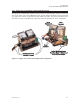
CHAPTER 5 REPLACEMENT PROCEDURES 5.2.20 CPU Board and Socketed IC Removals Refer to Figure 5-24, and proceed as follows: Note that the Motor driverand Serial driver ICs have socket mounts. If possible, attempt a repair by replacing one of these ICs. A repair made at this level should prove less costly in both time and material. Step 1. Remove the Rear Panel (see Section 5.2.1). Step 2. If replacement of a socketed component fails to effect a repair, proceed with step 3. Step 3.
CHAPTER 5 REPLACEMENT PROCEDURES 5.2.21 Extension PCBA Circuit Board and Socketed IC Replacements Several ICs on the Extension PCBA are socket mounted. As with the CPU board, repairs made at this level can prove less costly. In case of a motor problem, consider changing the dc motor driver IC U4, which is an L293. Refer to Figure 5-25, and proceed as follows: Step 1. Remove the Rear panel (see Section 3.5.1). Step 2. If IC replacement fails to effect a repair, proceed with step 3. Step 3.
CHAPTER 5 REPLACEMENT PROCEDURES 5.2.22 Clear Card Station Controller Board Replacements Before replacing the entire board, consider a repair by replacing one of the socketed ICs. To replace the board, refer to Figure 5-26, and proceed as follows: Step 1. Disconnect the six connectors. Note that three of the connectors have the same pin configurations, so consider identifying these connectors with tags to simplify installation. Step 2. Remove the two fasteners holding the board, and then remove the board.
CHAPTER 5 REPLACEMENT PROCEDURES 5.2.23 Power Supply Replacements Refer to Figure 5-27, and proceed as follows: Step 1. Remove Rear and Right side Case members (see Section 5.2.1). Step 2. Remove the four fasteners holding the Power Supply Shield to the Rear Plate, and separate the Shield. Step 3. Unplug the Power Supply ac input and dc output cables. Step 4. Remove the fasteners holding the Power Supply board to the Rear Plate. Figure 5-27. Power Supply Removal. 5-32 980286-001 Rev.
CHAPTER 5 REPLACEMENT PROCEDURES 5.2.24 Operator Panel Replacement Refer to Figure 5-28, and proceed as follows: Step 1. Swing down the Front Panel. Step 2. Unplug the Operator Panel connector from the CPU board. Step 3. Remove the three screws holding the Operator Panel Shield and underlying board. Step 4. Remove the board and switch assembly while feeding the cable through the associated chassis cutouts. Figure 5-28. Operator Panel Board Removal. 980286-001 Rev.
CHAPTER 5 REPLACEMENT PROCEDURES 5-34 980286-001 Rev.
CHAPTER 6 MAINTENANCE AND ADJUSTMENTS This chapter contains procedures for Cleaning and Adjustments. Other than cleaning and Cleaning Core replacement, no other regular maintenance requirements exist. Under no circumstances, should anyone ever apply either a lubricant or any other unprescribed material to a component inside the printer. No lubricated parts exist. Only 99-percent pure or better cleaning materials are specified here to minimize any chance of a residue.
CHAPTER 6 MAINTENANCE AND ADJUSTMENTS 6.1 CLEANING MATERIALS Figure 6-1 shows the cleaning materials available from 3M Products. The following table lists their use: Item Cleaned Item Used Part No. Print Head Swab 104526-001 Rollers Swab 104526-001 Card Path Items Cl;eaning Card 800104-004 NOTES: Swabs come in boxes of 25. Cards come in boxes of 50. Figure 6-1. Cleaning Materials 6.2 CLEANING Refer to the User's Guide for cleaning using the Cleaning Card.
CHAPTER 6 MAINTENANCE AND ADJUSTMENTS 6.2.1 Print Head Cleaning Refer to Figure 6-2, and proceed as follows: Step 1. Turn off power, open the Cover, and raise the Print Head. Step 2. Remove any ribbon installed. Step 3. For recently operated printers, the Print Head may be hot. If so, allow about a five-minute cool-down before proceeding. Step 4. Prepare a foam-tipped swab with alcohol, For 3M-supplied swabs, bend the foam tip until the underlying plastic breaks and releases the alcohol. Step 5.
CHAPTER 6 MAINTENANCE AND ADJUSTMENTS 6.2.2 Replacing Cleaning Roller Sheath Refer to Figure 6-3, and proceed as follows: Step 1. Turn off power, open the cover, and remove the Upper Cleaning Roller. Step 2. Slide off the old outer sheath, and replace it with a new one. Step 3. Reinstall the Cleaning Roller, and while avioding contact with the tacky surface of the roller, remove the protective tape. If necessary, turn the Manual Advance knob while removing the tape. Figure 6-3.
CHAPTER 6 MAINTENANCE AND ADJUSTMENTS 6.2.3 Cleaning Card-Feed and Card-Transport Rollers As shown in Figure 6-4, motor-driven rollers move the cards from the source roll and Feeder to the Output during printer operations. Except for the White Card Feed rollers and the Platen roller, all rollers have accompanying pressure rollers that keep the cards against the motor-driven rollers. The following procedure applies to all rollers except the Upper Cleaning Roller. Proceed as follows: Step 1.
CHAPTER 6 MAINTENANCE AND ADJUSTMENTS 6.3 ADJUSTMENTS Adjustments exist for the following: • Print Head Resistance • Peel Bar Position • Card Image Centering • Clear Card Pressure Roller Position • Belt Tension • See Appendix A for Potentiometer Adjustments. 6.3.1 Print Head Resistance The manufacturing process produces Print Heads with characteristics that vary slightly. Imaging results from the heat generated by the Print Head elements.
CHAPTER 6 MAINTENANCE AND ADJUSTMENTS Step 3. Position a 0.022-inch thick card in the card path under the Print Head. Step 4. Lower the Print Head to the latched-down position. Step 5. Issue a Head Down command (!D) from the Window’s print driver (see User’s manuals) or the Test Software (see Apendix A). Step 6. Push down on the Peel Bar until both ends of the Peel Bar rest on the card. Step 7.
CHAPTER 6 MAINTENANCE AND ADJUSTMENTS 6.3.3 Image Centering Centering establishes x- and y-offset values. The x offset determines when the Print Head lowers and raises, between which printing occurs. The y offset determines which group of Print Head elements produce images. If the Print Head lowers too soon, the leading card edge in encountering an already lowered Print Head can shear the ribbon.
CHAPTER 6 MAINTENANCE AND ADJUSTMENTS Step 4. Either measure or estimate any departure from a centered image, and convert the result to dots. Note that at 300 dpi, the distance between dots measures 0.00333... inches. Also, 300 dpi converts to 11.81 dots per millimeter, and the dot spacing measures 0.085 millimeters. Step 5. Either add or subtract (per the Remedy prescribed in table above) the Step-4 value(s) from the associated value(s) found on the Test Card printed in Step 1. Step 6.
CHAPTER 6 MAINTENANCE AND ADJUSTMENTS 6.3.4 Pressure Roller Position Card jams in the lower part of the Clear Card Feeder can result from a pressure roller not positioned parallel to the associated drive roller. To adjust this roller, refer to Figure 6-6, and proceed as follows: Step 1. Remove the rear and right case members (see Section 5.2.1). Step 2. Without unplugging its connectors, remove the White Card Feeder fasteners, and move the unit enough to access the Clear Card Feeder (see Section 5.2.2).
CHAPTER 6 MAINTENANCE AND ADJUSTMENTS 6.3.5 Stepper Belt Tension Adjustment Installation of Fixture 900116-001 applies pressure that pushes the Stepper Motor Pulley away from the Platen Pulley. Proceed as follows: Step 1. Remove the Printer Assembly and its rear plate (see Section 5.2.15). Step 2. Loosen the two screws holding the Stepper Motor. Step 3. Using a screwdriver as a pry-bar, pre-position the Stepper toward the lower-right quadrant of the panel cutout. Step 4.
CHAPTER 6 MAINTENANCE AND ADJUSTMENTS Step 5. Attach the Belt Tensioning Fixture between the Stepper and Platen pulleys (see Figure 6-8). Note how the fixture interfaces with the pulleys and belt. Figure 6-8. Stepper Motor Belt Tensioning Fixture. 6-12 980286-001 Rev.
CHAPTER 6 MAINTENANCE AND ADJUSTMENTS Step 6. As shown in Figure 6-9, use a screwdriver as a pry-bar to move the Stepper Motor away from the Ribbon Take Up Motor to a position the pointer on the fixture aligns with the center marker. Step 7. While holding the position established in Step 6, tighten the lower Stepper Motor Screw. Then, fully tighten the upper Stepper Motor Screw. Step 8.
CHAPTER 6 MAINTENANCE AND ADJUSTMENTS 6.3.6 Front Belt Tension Adjustments Installation of Fixtures C599 and C601 applies pressure that pulls the Belt Tensioning Idlers against the Front Timing belts. Refer to Figure 6-10, and proceed as follows: Step 1. Swing down the Front Panel. Step 2. Loosen the two screws holding each of the Belt Tension Idler Brackets. Step 3. Install the right (C599) and left (C601) Tensioning Fixtures between the Idler Pulleys and the top of the front plate. Step 4.
APPENDIX A TEST SOFTWARE Test Software supports factory procedures that contribute to a functioning Printer Module. This same software lets service personnel exercise the various functions of both the Printer Module and the companion Laminator and Die Cutter Module. Additionally, the software prompts the adjustment of potentiometers located on the circuit boards. Potentiometers establish the switching thresholds for the various sensors.
APPENDIX A TEST SOFTWARE The presentation here presumes a printer familiarity consistent with the information contained in other sections of this manual. Therefore, servicing personnel should have no trouble interpreting listed items. Begin by preparing the printer for operation, as follows: • Attach the required cables (see Section 2.1.4). • Install a ribbon (see Section 2.2.4). • Load Clear Card material and some White Cards (see Section 2.2.6 and 2.2.7). A.2.
APPENDIX A TEST SOFTWARE Particularly note the following: • A selection results by typing a list item number followed by . • Selection of Exit returns the DOS prompt. • Selection of “Change of COM port” should always follow the program launch to establish the port that has the printer attached. • Typing usually returns the previous screen. A.2.2 Changing the COM Port Note that the following screen, that appears with selection of Item 5.
APPENDIX A TEST SOFTWARE A.2.3 Operating in Terminal Mode The following screen appears following selection of item 4, Terminal Mode, from the first screen. Terminal Mode offers a convenient means for sending commands to the printer. This screen allows entry of all applicable commands found in the Programmer’s Manual. Before altering any of the parameters basic to printer operation, servicing personnel should record the current printer configuration (see “Printer Settings” in first screen).
APPENDIX A TEST SOFTWARE A.2.4 Typical Sub List Selection of Item 1, Printer Setting's [sic], from the first screen produces the following screen. which offers related selections. Note that many items in this list produce an observable action in the printer. Others present computer-prompted adjustment procedures. 980286-001 Rev.
APPENDIX A TEST SOFTWARE A.2.5 Typical Pot Adjustment Selection The following screen appears after selection of item 3, Sensors, from the previous screen. Continuing along the same path, the following screen appears with selection of Item 3, Color Sensor, from the previous screen. Properly setup, this sensor detects the yellow ribbon panel at Initialization.To locate the potentiometers related to sensor adjustments, see Figure 5-25. A-6 980286-001 Rev.
APPENDIX A TEST SOFTWARE A.2.6 Downloading Firmware Selection of item 16 from the Printer Setting's screen produces the following screen: Then, selection of Item 1, Download Frimware, produces the following screen(s), allowing entry of the firmware source: 980286-001 Rev.
APPENDIX A TEST SOFTWARE A-8 980286-001 Rev.
APPENDIX A TEST SOFTWARE 980286-001 Rev.