Domestic & Commercial Applications Operating & Fitting Instructions HOTRUN 35-90 ELECTRIC INSTANTANEOUS WATER HEATERS saving water and energy
Contents General information . . . . . . . . . . . . . . . . . . . . . . . . . . . . . . . . . Technical data . . . . . . . . . . . . . . . . . . . . . . . . . . . . . . . . . . . . . Safety instructions . . . . . . . . . . . . . . . . . . . . . . . . . . . . . . . . . . Mounting instructions . . . . . . . . . . . . . . . . . . . . . . . . . . . . . . . Water connection . . .
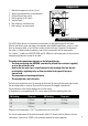
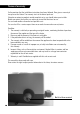
Components 1. Maximum temperature cut-out (a or b) 2. Second max.temperature cut-out (optional) 3. Differential pressure switch 4. Micro-switches of dP switch 5. Terminal block 6. Blue marking = cold water inlet 7.
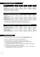
Technical specifications Model 35 46 60 72 90 Rating (kW) 3.5 4.6 6.0 7.2 9.0 Current (A) 16 20 25 2x16/32 2x20/40 Minimum pressure for all models: 1 bar / 100 kPa Maximum pressure for all models: 10 bar /1MPa Guaranteed Flow Rates at 37°C outlet temperature l/min when 1.9 2.5 3.6 4.0 5.1 4.3 5.4 7.5 8.4 10.5 inlet temp. = 12°C l/min when inlet temp.
Mounting instructions The screws and plugs are supplied with the unit. 1. Mark the position of the plugs according to the positional template allowing enough space around the Hotrun to open the Hotrun by removing the top and bottom screws if needed after installation. 2. Mount the unit using 2 screws. 3. Fit the top screw allowing it to stick out approximately 2-3 mm.
Point of use installation mains pressure Point of use installation Multipoint installation 6
Electric connection 1. Australian and New Zealand Standards wiring rules and guidelines must be adhered to. In most situations the installation of a 2-phase supply will be required for the Hotrun 72 and 90, to avoid voltage drop on a single phase supply/connection. 2. It is recommended to provide a dedicated circuit direct from the switchboard to each Hotrun. 3. The Hotrun has to be connected according to the applicable wiring diagram. 4. Check insulation resistance and proper earth continuity.
Initiation Attention: Avoid overheating Fill the unit completely with water before plugging it in or turning on the mains power supply. For that purpose: - Open the tap and wait until the water flows out from the spout without any air bubbles. - Close the tap. - Switch-on the mains supply. - Hotrun is ready to use. Maintenance Due to its advanced design the Hotrun does not need any maintenance. A damp cloth can be used for cleaning the cover. Scouring and dissolving agents are not suitable.
Troubleshooting Remedy - Fix the water pressure problems; remove any flow restrictors in outlets. - Switch the electric power supply off, check that there is no power on any of the terminals. - Seek electrical assistance to check power all the way to the elements. Problem 2 - The water that is coming out of the Hotrun is not warm enough. Cause - The incoming water is very cold (below 12°C) - The total flow is too high. Remedy - A flow restrictor should have been installed.
Technische Terms of warranty gegevens On the provision that the installation instructions have been followed, Elwa gives a warranty of two years on the Hotrun. The warranty starts at the date of purchase. If despite our extensive products control complaints arise, you should inform your installer. Before you contact the installer, we advise you to read the directions for use. You can avoid needless discomfort and possible costs. You can also fill in a service request form on our web-site www.elwa.com.
Flexible hose instructions For the range with built-in flow control: 1.9 l/min hotrun 35 2.5 l/min hotrun 46 3.0 l/min hotrun 60 4.0 l/min hotrun 72 5.
Elwa Pty Ltd Adelaide Australia Phone: +61 8 8353 4040 www.elwa.com.au Email: service@elwa.com.au Elwa Pty Ltd Auckland New Zealand Phone +64 21 280 173 www.elwa.co.nz Email: service@elwa.co.nz Elwa BV Amsterdam The Netherlands Tel.+31 20 436 1224 www.elwa.nl Email: service@elwa.nl AS/NZS 3498 40034 version 2/2013 Approvals to Australian/New Zealand standards: AS/NZS 60335.2.