
Technical data


10
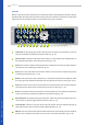
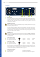
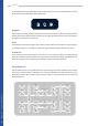
In the middle of the unit, right below the gain reduction meters, there are three buttons to set the
distinct operating modes of the alpha compressor:
M/S Mode
If this button is pressed, the alpha compressor will work in M/S mode in which the controls on the
left side aect the middle channel and those on the right side belong to the side channel. Other-
wise the unit will work in stereo mode.
Active
If this button is pressed (LED glows), the incoming signals will be processed by the alpha compres-
sor. Otherwise there is a hard bypass, whereas the gain reduction meters will still stay active.
Channel Link
If this button is pressed, the left upper array will act as a master for the dynamic sections of both
channels. All other parameters (lter, mix, gain, limiter) are not linked, though, and therefore have
to be set manually. In this mode the gain reduction is identical for both channels.
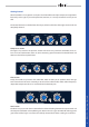
Signal Flowchart
The schematic shows the signal ow from the input through the specic modules to the output.
M/S matrix, sidechain lters, audio lters, mix stages, transformers and Soft Clip limiters can be
optionally switched into the signal path via relays, which is also true of the Auto Fast and feed
forward functions.
Input
Transformer
Input
Buer
Left
Input
Sidechain
Filter
Sidechain
Compressor
Audio
Filter
Gainreduction
Meter
Transformer
Mix
Stage
Gain
Stage
Output
Amp
Soft Clip
Limiter
M/S Encoder
M/S Decoder
Input
Transformer
Right
Input
Input
Buer
Compressor
Sidechain
Sidechain
Filter
Audio
Filter
Gainreduction
Meter
Gain
Stage
Mix
Stage
Transformer
Right
Output
Output
Amp
Soft Clip
Limiter
Left
Output
M/S Mode Active Channel Link
BASICS – Signal Flowchart
BASICS