
Manual


7
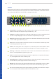
EQ Freq: the center frequency of the Niveau Filter. Around this reference point, bass is
boosted and treble is cut or vice versa. (pp. 11, 21)
x10: shifts the frequency range of the Niveau Filter. The printed values from 26 Hz to 2.2 kHz
are multiplied by 10 to 260 Hz and 22 kHz. (pp. 11, 21)
GR Limit: margins the control voltage. This innovative limiter is not placed in the audio path
as usual, but in the control circuit of the compressor. (pp. 11, 23)
On: activates the Gain Reduction Limiter. Similar to the other functions, this module is
switched into the signal path via relay. (pp. 11, 23)
Gain: the ‘make up gain‘. In the mpressor, amplication already takes place in the input
stage, thus the complete circuitry can be driven harder on purpose. (p. 18)
GRL: indicates Gain Reduction Limiter activity. In link mode, the indicator LEDs of both chan-
nels always light up simultaneously. (pp. 11, 23)
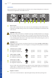
Left/Right: activates the respective channel of the compressor. In deactivated state, the in-
put is directly routed to the output by a hardwire bypass. (p. 9)
Link: both channels can be operated in combination with the left control panel as master.
Note: EQ sections and gain stages will not be linked in this mode! (p. 9)
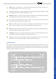
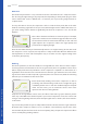
Signal Flowchart
The schematic shows the signal ow from the input through the specic modules to the out-
put. External sidechain, link function, Gain Reduction Limiter and Niveau Filter can be optionally
switched into the signal path via relays. The compression stages continuously work in feed for-
ward mode with a hard knee characteristic.
BASICS – Signal Flowchart
Left Audio
Input
Input
Stage
Left Audio
Output
Sidechain
Stage
Left Sidechain
Input
Gain
Stage
Output
Stage
Transconduc-
tance Amp
Current to
Voltage
Audio
Filter
Gain Reduction
Meter
Gain Reduction
Limiter
Right Audio
Input
Input
Stage
Right Audio
Output
Sidechain
Stage
Right Sidechain
Input
Gain
Stage
Output
Stage
Transconduc-
tance Amp
Current to
Voltage
Audio
Filter
Gain Reduction
Meter
Gain Reduction
Limiter