eMachines E510 Series Service Guide Service guide files and updates are available on the ACER/CSD web; for more information, please refer to http://csd.acer.com.
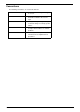
Revision History Please refer to the table below for the updates made on Aspire Nettling service guide.
Copyright Copyright © 2008 by Acer Incorporated. All rights reserved. No part of this publication may be reproduced, transmitted, transcribed, stored in a retrieval system, or translated into any language or computer language, in any form or by any means, electronic, mechanical, magnetic, optical, chemical, manual or otherwise, without the prior written permission of Acer Incorporated. Disclaimer The information in this guide is subject to change without notice.
Conventions The following conventions are used in this manual: IV SCREEN MESSAGES Denotes actual messages that appear on screen. NOTE Gives bits and pieces of additional information related to the current topic. WARNING Alerts you to any damage that might result from doing or not doing specific actions. CAUTION Gives precautionary measures to avoid possible hardware or software problems. IMPORTANT Reminds you to do specific actions relevant to the accomplishment of procedures.
Preface Before using this information and the product it supports, please read the following general information. 1. This Service Guide provides you with all technical information relating to the BASIC CONFIGURATION decided for Acer's "global" product offering. To better fit local market requirements and enhance product competitiveness, your regional office MAY have decided to extend the functionality of a machine (e.g. add-on card, modem, or extra memory capability).
VI
Chapter 1 System Specifications Features Below is a brief summary of the computer’s many feature: Operating System • Genuine Windows® VistaTM Capable • Genuine Windows® VistaTM Home Basic / Home Premium / Ultimate / Business Edition • Genuine Windows® XP Home / Professional Edition (Service Pack 2) • Genuine Windows® XP Media Center / Tablet Edition • Genuine Windows® 2000 (Service Pack 4) NOTE: Windows® VistaTM Capable PCs come with Windows® XP installed, and can be upgraded to Windows® VistaTM.
• Built-in microphone Dimensions and Weight • 366 (W) x 274 (D) x 33.6/42.6 (H) mm (14.4 x 10.78 x 1.32/1.67 inches) • 2.8 kg (6.16 lbs.
• Chapter 1 • Operating: 5 °C to 35 °C • Non-operating: -20 °C to 65 °C Humidity (non-condensing): • Operating: 20% to 80% • Non-operating: 20% to 80% 3
System Block Diagram 4 Chapter 1
Board Layout Top View 1 2 3 4 8 9 7 5 6 10 15 11 16 12 1 13 14 JP1 LCD Connector 9 JP36 2 JP3 Speaker (Left) Connector 10 U12 3 JP34 Speaker (Right) Connector 11 JP9 PCI Express Card Socket 4 JP4 Internal MIC Connector 12 LED1 Power/Suspend LED 5 U5 South Bridge (ICH8M) 13 LED2 Battery Charge/Discharge LED 6 JP6 Internal Track-Pad Connector 14 JP13 Mainboard to Audio Board Connector 7 JP5 Internal Keyboard Connector 15 JP11 Mainboard to USB Board Connector
Bottom View 1 3 2 4 10 9 8 5 6 11 12 7 13 17 14 15 16 18 19 20 24 21 22 23 6 25 1 PJP1 DC-in Power Jack 14 JP24 TV-out Connector 2 PJP2 Battery Connector 15 JP26 IEEE1394 Connector 3 JP14 CRT Connector 16 JP27 SATA HDD Connector 4 JP15 DVI-D Connector 17 U23 North Bridge (965PM/965GM) 5 JP25 ODD Connector 18 U28 6 JP20 Mini Card (WLAN) Socket 19 U29 Volume Control 7 JP19 Mini Card (TV-Tuner) Socket 20 JP28 DDRII Memory Socket 8 JP17 MDC Connector 21 J
Your Acer Notebook Tour After knowing your computer features, let us show you around your new Aspire computer. Front View # Chapter 1 Icon Item Description 1 Built-in camera 0.3 megapixel web camera for video communication. 2 Power button Turns the computer on and off. 3 Easy-launch buttons Buttons for launching frequently used programs. 4 Wireless communication button/indicator Enables/disables the wireless function. Indicates the status of wireless LAN communication.
6 Keyboard For entering data into your computer. 7 Touchpad Touch-sensitive pointing device which functions like a computer mouse. 8 Click buttons (left, center, and right) The left and right buttons function like the left and right mouse buttons. 9 Microphone Internal microphone for sound recording. 10 Display screen Also called Liquid-Crystal Display (LCD), displays computer output.
Left View # Icon Item Description 1 Kensington lock slot Connects to a Kensington-compatible computer security lock. 2 External display (VGA) port Connects to a display device (e.g., external monitor, LCD projector). DVI DVI-D port Supports digital video connections. 4 Ethernet (RJ-45) Connects to an Ethernet 10/100/1000based network (for selected models). 5 2 USB 2.0 port Connect to USB 2.0 devices (e.g., USB mouse, USB camera).
Right View # Icon Item Description 1 2 USB 2.0 ports Connect to USB 2.0 devices (e.g., USB mouse, USB camera). 2 AV-in port Accepts input signals from audio/video (AV) devices. 3 Optical drive Internal optical drive; accepts CDs or DVDs (slot-load or tray-load depending on model). 4 Optical disk access indicator Lights up when the optical drive is active. 5 Optical drive eject button Ejects the optical disk from the drive.
Base view # Item Description 1 Battery bay Houses the computer’s battery pack. 2 Battery release latch Releases the battery for removal. 3 Battery lock Locks the battery in position. 4 Hard disk bay Houses the computer’s hard disk (secured with screws) 5 Ventilation slots and cooling fan Enable the computer to stay cool, even after prolonged use. Note: Do not cover or obstruct the opening of the fan. Indicators The computer has several easy-to-read status indicators.
Icon Function Description Power Lights up when the computer is on. Battery Lights up when the battery is being charged. Wireless LAN Indicates the status of wireless LAN communication. Bluetooth Indicates the status of Bluetooth communication. HDD Indicates when the hard disc or optical drive is active. Num lock Lights when Num Lock is activated. Cap lock Lights when Cap Lock is activated NOTE: 1. Charging: The light shows amber when the battery is charging. 2.
Launch Button Default application Acer Empowering Technology (user-programmable) Web browser Internet browser (user-programmable) Mail Email application (user-programmable) Arcade Windows Media Center Touchpad Basics The following teaches you how to use the touchpad: T Move your finger across the touchpad (2) to move the cursor. T Press the left (1) and right (4) buttons located beneath the touchpad to perform selection and execution functions.
Using the Keyboard The keyboard has full-sized keys and an embedded keypad, separate cursor keys, one Windows key and twelve function keys. Lock Keys and embedded numeric keypad The keyboard has three lock keys which you can toggle on and off. Lock Key Description Caps Lock When Caps Lock is on, all alphabetic characters typed are in uppercase. Num lock + When Num Lock is on, the embedded keypad is in numeric mode.
Key Icon Windows key Description Pressed alone, this key has the same effect as clicking on the Windows Start button; it launches the Start menu. It can also be used with other keys to provide a variety of function: + Activates next taskbar button. + Opens the My Computer window + Opens Help and Support. + Opens the Search: All Files dialog box. + Opens the Run dialog box. + Minimizes all windows. + action.
Hot Key Icon Function Description + Display toggle Switches display output between the display screen, external monitor (if connected) and both. + Screen blank Turns the display screen backlight off to save power. Press any key to return. + Touchpad toggle Turns the internal touchpad on and off. + Speaker toggle Turns the speakers on and off. + Brightness up Increases the screen brightness.
The US dollar sign 1. Open a text editor or word processor. 2. Either directly press the < > key at the bottom-right of the keyboard, or hold and then press the <4> key at the upper-center of the keyboard. NOTE: This function varies by the operating system version.
Hardware Specifications and Configurations Processor Item Specification CPU type Intel® Celeron (Santarosa) processor Core logic Intel® GL960 Express chipset CPU package Intel socket 1466pin FCBGA CPU core voltage 0.944~1.
Item Specification Memory size 0MB (no on-board memory) DIMM socket number 2 sockets Supports memory size per socket 2 GB Supports maximum memory size 4G for 64bit OS (with two 2GB SODIMM) Supports DIMM type DDR 2 Synchronous DRAM Supports DIMM Speed 667/800 MHz Supports DIMM voltage 1.8V and 0.9V Supports DIMM package 200-pin soDIMM Memory module combinations You can install memory modules in any combinations as long as they match the above specifications.
LAN Interface Item Specification Chipset Atheros / Broadcom Supports LAN protocol 10/100/1000 Ethernet Giga LAN Features PCI-E Giga LAN Support Wake-On-Lan (AC mode S5) No ASF 2.0/iAMT 4.0 Wireless Module 802.11b/g Item Specification Chipset Intel Shirley Peak and Echo Peak (for Centrino platform) Atheros WLAN XB63 and Broadcom WLAN BCM4312 (for Non-Centrino) Data throughput 11~54 Mbps, up to 270 Mbps for Draft-N Protocol 802.
Item Specification Performance Specification With CD Diskette With DVD Diskette Transfer rate (KB/sec) Sustained: Max 3.6Mbytes/ sec Sustained: Max 10.8Mbytes/sec Buffer Memory 2MB Interface Enhanced IDE(ATAPI) compatible Applicable disc format Support disc formats 1. Reads data in each CD-ROM, CD-ROM XA, CD1, Video CD, CD-Extra and CD-Text 2. Reads data in Photo CD (single and Multi-session) 3. Reads standard CD-DA 4. Reads and writes CD-R discs 5. Reads and writes CD-RW discs 6.
Item Specification Supports card type Type-II Number of slots One type-II Access location Left side Supports ZV (Zoomed Video) port No ZV support Supports 32 bit CardBus Yes System Board Major Chips Item Controller Core logic Intel® 965PM/965GM+ICH8M LAN Broadcom 5787 USB 2.
LCD 15.4” Specificatio n Item Vendor & model name LPL LP154WX4TL B2 (G) CMO N154I2L05 GLARE AUO B154EW0 2 V7(G) SAMSUNG LTN154AT010 01(G) Screen Diagonal (mm) 15.4 inches 15.4 inches 15.4 inches 15.4 inches Active Area (mm) 304.1x228.1 304.1x228.1 304.1x228 .1 Display resolution (pixels) 1440x900 WXGA+ 1440x900 WXGA+ 1440x900 WXGA+ Pixel Pitch 0.297x0.297 0.099x0.297 0.297x0.2 97 Pixel Arrangement R.G.B. Vertical Stripe R.G.B. Vertical Stripe R.G.B. Vertical Stripe R.G.B.
LCD Inverter Item Specification Vendor & model name Darfon/V189-301GP Brightness conditions N/A Input voltage (V) 9~21 Input current (mA) 2.56 (max) Output voltage (V, rms) 780V (2000V for kick off) Output current (mA, rms) 6.5 (max) Output voltage frequency (k Hz) 65K Hz (max) AC Adapter Item Specification Input rating 100~240Vac/ 65Hz Maximum input AC current 1.75A Inrush current 220A@115VAC 220A@230VAC Efficiency 82% min.
System Power Management ACPI mode Power Management Working (G0/S0) Individual devices such as the CPU and hard disc may be power managed in this state. Suspend to RAM (S3) CPU set power down VGA Suspend PCMCIA Suspend Audio Power Down Hard Disk Power Down CD-ROM Power Down Super I/O Low Power mode Save to Disk (S4) Also called Hibernation Mode. System saves all system states and data onto the disc prior to power off the whole system.
38 Chapter 1
Chapter 2 System Utilities BIOS Setup Utility The BIOS Setup Utility is a hardware configuration program built into your computer’s BIOS (Basic Input/ Output System). Your computer is already properly configured and optimized, and you do not need to run this utility. However, if you encounter configuration problems, you may need to run Setup. Please also refer to Chapter 4 Troubleshooting when problem arises.
Navigating the BIOS Utility There are six menu options: Info., Main, System Devices, Security, Boot, and Exit. Follow these instructions: T To choose a menu, use the cursor left/right keys (zx). T To choose a parameter, use the cursor up/down keys (wy). T To change the value of a parameter, press por q. T A plus sign (+) indicates the item has sub-items. Press e to expand this item. T Press ^ while you are in any of the menu options to go to the Exit menu.
Information InsydeH2O Setup Utility Information Main Security Advanced Boot CPU Type : CPU Speed : Intel (R) Core(TM)2 Duo CPU 2.00 GHz HDD Model Name : HDD Serial Number : ATAPI Model Name : ATAPI Serial Number: Hitachi HTS541616J9SA00 xxxxxxxxxxxxxxxxxxxxxx TOSHIBA DVDW/HD TS-L802A xxxxxxxxxxxxxxxxxxxxxx System BIOS Version: VGA BIOS Version: Serial Number: Asset Tag Number: Product Name: Manufacturer Name: UUID: V0.18.
Main The Main screen displays a summary of your computer hardware information, and also includes basic setup parameters. It allows the user to specify standard IBM PC AT system parameters.
The table below describes the parameters in this screen. Settings in boldface are the default and suggested parameter settings. Parameter Description Format/Option System Time Sets the system time. The hours are displayed with 24-hour format. Format: HH:MM:SS (hour:minute:second) System Time System Date Sets the system date. Format MM/DD/YYYY (month/day/ year) System Date System Memory This field reports the memory size of the system.
Advanced The Advanced screen displays advanced settings in BIOS. InsydeH2O Setup Utility Information Main Security Advanced Boot Exit Item Specific Help Advanced CPU Control Platform Power Management These items control various CPU parameters.
Security The Security screen contains parameters that help safeguard and protect your computer from unauthorized use. InsydeH2O Setup Utility Information Main Security Advanced Boot Exit Item Specific Help Supervisor Password Is User Password Is HDD Password Clear Clear Clear Set Supervisor Password Set User Password Set HDD Password [Enter] [Enter] [Enter] Password on Boot : [Enabled] Install or Change the password.
The table below describes the parameters in this screen. Settings in boldface are the default and suggested parameter settings. Parameter Description Option Supervisor Password is Shows the setting of the Supervisor password Clear or Set User Password is Shows the setting of the user password. Clear or Set HDD Password Shows the setting of the hard disk password. Clear or Set Set Supervisor Password Press Enter to set the supervisor password.
Removing a Password Follow these steps: 1. Use the w and y keys to highlight the Set Supervisor Password parameter and press the e key. The Set Supervisor Password box appears: 2. Type the current password in the Enter Current Password field and press e. 3. Press e twice without typing anything in the Enter New Password and Confirm New Password fields. The computer then sets the Supervisor Password parameter to “Clear”. 4.
If the current password entered does not match the actual current password, the screen will show you the Setup Warning. If the new password and confirm new password strings do not match, the screen will display the following message.
Boot This menu allows the user to decide the order of boot devices to load the operating system. Bootable devices includes the diskette drive in module bay, the onboard hard disk drive, and the CD-ROM in module bay. InsydeH2O Setup Utility Information Main Security Advanced Boot Exit Item Specific Help Boot Priority Order: 1: 2: 3: 4: 5: 6: 7: Use < > or < > to select a device, then press to move it up the list, or to move it down the list. Press to escape the menu.
Exit The Exit screen contains parameters that help safeguard and protect your computer from unauthorized use. InsydeH2O Setup Utility Information Main Security Advanced Boot Exit Item Specific Help Exit Saving Changes Exit Discarding Changes Load Setup Defaults Discard Changes Save Changes Exit System Setup and save your changes to CMOS.
BIOS Flash Utility The BIOS flash memory update is required for the following conditions: T New versions of system programs T New features or options T Restore a BIOS when it becomes corrupted. Use the Phlash utility to update the system BIOS flash ROM. NOTE: If you do not have a crisis recovery diskette at hand, then you should create a Crisis Recovery Diskette before you use the Phlash utility. NOTE: Do not install memory-related drivers (XMS, EMS, DPMI) when you use the Phlash.
52 Chapter 2
Chapter 3 Machine Disassembly and Replacement This chapter contains step-by-step procedures on how to disassemble the notebook computer for maintenance and troubleshooting. To disassemble the computer, you need the following tools: T Wrist grounding strap and conductive mat for preventing electrostatic discharge T Small Philips screw driver T Philips screwdriver T Plastic flat head screw driver T Tweezers NOTE: The screws for the different components vary in size.
General Information Before You Begin Before proceeding with the disassembly procedure, make sure that you do the following: 54 1. Turn off the power to the system and all peripherals. 2. Unplug the AC adapter and all power and signal cables from the system. 3. Remove the battery pack.
Disassembly Procedure Flowchart The flowchart on the succeeding page gives you a graphic representation on the entire disassembly sequence and instructs you on the components that need to be removed during servicing. For example, if you want to remove the system board, you must first remove the keyboard, then disassemble the inside assembly frame in that order.
LCD Module B*4 LCD Bezel G*1 for 15" G*2 for 15.4" LCD Inverter B*2 LCD Assembly LCD Panel G*2 for 15.4" Wireless Antenna Set F*8 (4 on left; 4 on right) LCD Bracket Sets LCD Cable LCD Screw List Item A 56 Description SCREW M2.5*3(NL) Part Number 86.TAVV5.001 B SCREW M2.5*6(NL) 86.TAVV5.002 C SCREW M2.5*10(NL) 86.TAVV5.003 D SCREW M2.5*15(NL) 86.TAVV5.004 E SCREW M2*2.2 86.TAVV5.005 F SCREW M2*3(NL) 86.TAVV5.006 G SCREW M2*4 86.TAVV5.007 H SCREW M3*4(NL) 86.TAVV5.
Removing the Battery Pack 1. Unlock the battery lock (move the battery lock to the unlock position as shown). 2. Slide the battery release latch then remove the battery.
Removing the HDD Module/Memory/Wireless LAN Card/Modem Card/ TV Tuner Card/System Fan/Thermal Modules/VGA Board/CPU/ Keyboard and the LCD Module Removing the HDD Module 1. Remove the two screws fastening the HDD cover. 2. Detach the HDD cover from the main unit. 3. Pull the tab to remove the HDD module in the direction of the arrow. Removing the Memory 1. Remove the four screws holding the thermal cover. 2. Detach the thermal cover from the main unit. 3.
4. Remove the screw fastening the modem card and detach the modem card from the main board. 5. Disconnect the RJ-11 cable and remove the modem card. 6. Disconnect the RF cable from the TV tuner card. 7. Remove the two screws fastening the TV tuner card. 8. Then take out the TV tuner card from the main unit. NOTE: TV tuner card on selected models only.
Removing the System Fan/Thermal Modules/VGA Board and CPU 1. Disconnect the fan cable from the main board. 2. Remove the three screws holding the system fan. 3. Remove the four spring screws holding the CPU thermal module. 4. Then detach the CPU thermal module as shown. 5. Remove the four spring screws holding the VGA thermal module. 6. Then detach the VGA thermal module as shown. 7. Remove the two screws fastening the VGA board then remove it. 8.
Removing the Keyboard and LCD Module 1. Turn the notebook over. 2. Remove the two screws securing the strip cover from the bottom of the notebook. 3. Detach the strip cover from the front side and remove it. 4. Gently pull up the keyboard to release it from the four snaps as shown. 5. Turn over the keyboard as the image shows. Then disconnect the keyboard cable from the main board. 6. Remove the keyboard from the main unit. 7. Disconnect the LCD cable and microphone cable from the main board.
10. Detach the LCD module from the main unit.
Disassembling the Main Unit Separate the Main Unit Into the Upper and the Lower Case Assembly 1. Remove the screw fastening the ODD from the bottom of the notebook. 2. Push the ODD module outwards and gently pull it out as shown. 3. Press and release the PC dummy card from the PC slot as shown. 4. Then press the release the memory dummy card from the 5-in-1 card reader slot as shown. 5. Remove the ten screws fastening the upper case and the lower case assembly on the bottom. 6.
7. Disconnect the touchpad FFC, left speaker cable, button board FFC, and LED board FFC from the main board. 8. Carefully detach the upper case assembly from the lower case assembly. Disassembling the Lower Case Assembly 64 1. Disconnect the USB cable from the main board. 2. Remove the screw fastening the USB board and take out the board and its cable from the lower case. 3. Then detach the USB cable from the USB board. 4. Disconnect the Bluetooth cable from the main board. 5.
9. Pull the RF cable through the opening in the lower case as shown. 10. Remove the screw holding the RF board to the lower case. 11. Take out the RF board from the lower case, then detach the RF cable from the RF board as shown. 12. Remove the RJ-11 jack from the lower case. NOTE: RF board on selected models only. 13. Remove the screw fastening the main board to the lower case. 14. Detach the main board from the lower case as shown. 15.
Disassembling the Upper Case Assembly 66 1. Turn the upper case over. 2. Remove the two screws fastening the button board. 3. Detach the button board with FFC from the upper case as shown. 4. Remove the two screws fastening the LED board. 5. Detach the LED board with FFC from the upper case as shown. 6. Remove the two screws fastening the left speaker. 7. Remove the left speaker from the upper case as shown.
Disassembling the LCD Module 1. Remove the four screw rubbers as shown. 2. Then remove the four screws fastening the LCD bezel. 3. Detach the LCD bezel from the LCD module carefully. 4. Remove the four screws holding the LCD to the LCD panel. 5. Detach the CCD cable connector from the CCD board. 6. Take out the CCD module from the LCD panel. 7. Remove the screw fastening the CCD board to the CCD bracket. 8. Lift out the LCD from the LCD panel as shown. 9.
68 Chapter 3
Disassembling the External Modules Disassembling the HDD Module 1. Remove the four screws holding the HDD (hard disk drive) case; two on each side. 2. Carefully slide out the hard disk drive from the HDD case. Disassembling the ODD Module 1. Remove the three screws holding the optical bracket. 2. Then remove the optical bracket from the optical disk drive.
70 Chapter 3
Chapter 4 Troubleshooting Use the following procedure as a guide for computer problems. NOTE: The diagnostic tests are intended to test only Acer products. Non-Acer products, prototype cards, or modified options can give false errors and invalid system responses. 1. Obtain the failing symptoms in as much detail as possible. 2. Verify the symptoms by attempting to re-create the failure by running the diagnostic test or by repeating the same operation. 3.
System Check Procedures External Diskette Drive Check Do the following to isolate the problem to a controller, driver, or diskette. A write-enabled, diagnostic diskette is required. NOTE: Make sure that the diskette does not have more than one label attached to it. Multiple labels can cause damage to the drive or cause the drive to fail. Do the following to select the test device: 1. Boot from the diagnostics diskette and start the diagnostics program. 2.
If any of these devices do not work, reconnect the cable connector and repeat the failing operation. Memory check Memory errors might stop system operations, show error messages on the screen, or hang the system. 1. Boot from the diagnostics diskette and start the doagmpstotics program (please refer to main board). 2. Go to the diagnostic memory in the test items. 3. Press F2 in the test items. 4. Follow the instructions in the message window.
Check the Power Adapter Unplug the power adapter cable from the computer and measure the output voltage at the plug of the power adapter cable. See the following figure: Pin 1: +19 to +20.5V Pin 2: 0V, Ground 1. If the voltage is not correct, replace the power adapter. 2. If the voltage is within the range, do the following: T Replace the System board. T If the problem is not corrected, see “Undetermined Problems” on page 88. If the voltage is not correct, go to the next step.
Check the Battery Pack To check the battery pack, do the following: From Software: 1. Check out the Power Management in Control Panel 2. In Power Meter, confirm that if the parameters shown in the screen for Current Power Source and Total Battery Power Remaining are correct. 3. Repeat the steps 1 and 2, for both battery and adapter. 4. This helps you identify first the problem is on recharging or discharging. From Hardware: 1. Power off the computer. 2.
Power-On Self-Test (POST) Error Message The POST error message index lists the error message and their possible causes. The most likely cause is listed first. NOTE: Perform the FRU replacement or actions in the sequence shown in FRU/Action column, if the FRU replacement does not solve the problem, put the original part back in the computer. Do not replace a non-defective FRU. This index can also help you determine the next possible FRU to be replaced when servicing a computer.
Index of Error Messages Error Code List Error Codes 006 Error Messages Equipment Configuration Error Causes: 1. CPU BIOS Update Code Mismatch 2. IDE Primary Channel Master Drive Error (THe causes will be shown before “Equipment Configuration Error”) 010 Memory Error at xxxx:xxxx:xxxxh (R:xxxxh, W:xxxxh) 070 Real Time Clock Error 071 CMOS Battery Bad 072 CMOS Checksum Error 110 System disabled. Incorrect password is specified.
Error Message List Error Messages Real time clock error FRU/Action in Sequence RTC battery Run BIOS Setup Utility to reconfigure system time, then reboot system. System board Previous boot incomplete - Default configuration used Run “Load Default Settings” in BIOS Setup Utility. RTC battery System board Memory size found by POST differed from CMOS Run “Load Default Settings” in BIOS Setup Utility.
Error Message List No beep Error Messages No beep, power-on indicator turns off and LCD is blank. FRU/Action in Sequence Power source (battery pack and power adapter). See “Power System Check” on page 73.. Ensure every connector is connected tightly and correctly. Reconnect the DIMM. LED board. System board. No beep, power-on indicator turns on and LCD is blank. Power source (battery pack and power adapter). See “Power System Check” on page 73..
Phoenix BIOS Beep Codes Code Beeps 02h Verify Real Mode 03h Disable Non-Maskable Interrupt (NMI) 04h Get CPU type 06h Initialize system hardware 08h Initialize chipset with initial POST values 09h Set IN POST flag 0Ah Initialize CPU registers 0Bh Enable CPU cache 0Ch Initialize caches to initial POST values 0Eh Initialize I/O component 0Fh Initialize the local bus IDE 10h Initialize Power Management 11h Load alternate registers with initial POST values 12h Restore CPU control wo
Code 46h Beeps 2-1-2-3 48h POST Routine Description Check ROM copyright notice Check video configuration against CMOS 49h Initialize PCI bus and devices 4Ah Initialize all video adapters in system 4Bh QuietBoot start (optional) 4Ch Shadow video BIOS ROM 4Eh Display BIOS copyright notice 50h Display CPU type and speed 51h Initialize EISA board 52h Test keyboard 54h 58h Set key click if enabled 2-2-3-1 Test for unexpected interrupts 59h Initialize POST display service 5Ah Display pro
Code Beeps 8Ch Initialize floppy controller 8Fh Determine number of ATA drives (optional) 90h Initialize hard-disk controllers 91h Initialize local-bus hard-disk controllers 92h Jump to UserPatch2 93h Build MPTABLE for multi-processor boards 95h Install CD ROM for boot 96h Clear huge ES segment register 97h 98h Fixup Multi Processor table 1-2 Search for option ROMs. One long, two short beeps on checksum failure.
Code Beeps D2h POST Routine Description Unknown interrupt Code Beeps E0h Initialize the chipset E1h Initialize the bridge E2h Initialize the CPU E3h Initialize the system timer E4h Initialize system I/O E5h Check force recovery boot E6h Checksum BIOS ROM E7h Go to BIOS E8h Set Huge Segment E9h Initialize Multi Processor EAh Initialize OEM special code EBh Initialize PIC and DMA ECh Initialize Memory type EDh Initialize Memory size EEh Shadow Boot Block EFh System memory
Index of Symptom-to-FRU Error Message LCD-Related Symptoms Symptom / Error LCD backlight doesn't work Action in Sequence LCD is too dark Enter BIOS Utility to execute “Load Setup Default Settings”, then reboot system. LCD brightness cannot be adjusted Reconnect the LCD connectors. LCD contrast cannot be adjusted Keyboard (if contrast and brightness function key doesn't work).
Power-Related Symptoms Symptom / Error Battery can’t be charged Action in Sequence See “Check the Battery Pack” on page 75. Battery pack System board PCMCIA-Related Symptoms Symptom / Error System cannot detect the PC Card (PCMCIA) Action in Sequence PCMCIA slot assembly System board PCMCIA slot pin is damaged. PCMCIA slot assembly Memory-Related Symptoms Symptom / Error Memory count (size) appears different from actual size.
Power Management-Related Symptoms Symptom / Error Battery fuel gauge in Windows doesn’t go higher than 90%. Action in Sequence Remove battery pack and let it cool for 2 hours. Refresh battery (continue use battery until power off, then charge battery). Battery pack System board System hangs intermittently. Reconnect hard disk/CD-ROM drives. Hard disk connection board System board Peripheral-Related Symptoms Symptom / Error Action in Sequence System configuration does not match the installed devices.
Intermittent Problems Intermittent system hang problems can be caused by a variety of reasons that have nothing to do with a hardware defect, such as: cosmic radiation, electrostatic discharge, or software errors. FRU replacement should be considered only when a recurring problem exists. When analyzing an intermittent problem, do the following: 1. Run the advanced diagnostic test for the system board in loop mode at least 10 times. 2. If no error is detected, do not replace any FRU. 3.
Undetermined Problems The diagnostic problems does not identify which adapter or device failed, which installed devices are incorrect, whether a short circuit is suspected, or whether the system is inoperative. Follow these procedures to isolate the failing FRU (do not isolate non-defective FRU). NOTE: Verify that all attached devices are supported by the computer. NOTE: Verify that the power supply being used at the time of the failure is operating correctly. (See “Power System Check” on page 73.): 88 1.
Chapter 5 Jumper and Connector Locations Top View 1 2 3 4 8 9 7 5 6 10 15 11 16 12 1 13 14 JP1 LCD Connector 9 JP36 2 JP3 Speaker (Left) Connector 10 U12 3 JP34 Speaker (Right) Connector 11 JP9 PCI Express Card Socket 4 JP4 Internal MIC Connector 12 LED1 Power/Suspend LED 5 U5 South Bridge (ICH8M) 13 LED2 Battery Charge/Discharge LED 6 JP6 Internal Track-Pad Connector 14 JP13 Mainboard to Audio Board Connector 7 JP5 Internal Keyboard Connector 15 JP11 Mai
Bottom View 1 3 2 4 10 9 8 5 6 11 12 7 13 17 14 15 16 18 19 20 24 21 22 23 90 25 1 PJP1 DC-in Power Jack 14 JP24 TV-out Connector 2 PJP2 Battery Connector 15 JP26 IEEE1394 Connector 3 JP14 CRT Connector 16 JP27 SATA HDD Connector 4 JP15 DVI-D Connector 17 U23 North Bridge (965PM/965GM) 5 JP25 ODD Connector 18 U28 6 JP20 Mini Card (WLAN) Socket 19 U29 Volume Control 7 JP19 Mini Card (TV-Tuner) Socket 20 JP28 DDRII Memory Socket 8 JP17 MDC Connector 21
Chapter 6 FRU (Field Replaceable Unit) List This chapter gives you the FRU (Field Replaceable Unit) listing in global configurations of Aspire eME510. Refer to this chapter whenever ordering for parts to repair or for RMA (Return Merchandise Authorization). Please note that WHEN ORDERING FRU PARTS, you should check the most up-to-date information available on your regional web or channel. For whatever reasons a part number change is made, it will not be noted on the printed Service Guide.
Aspire eME510 Exploded Diagram Aspire eME510 FRU List Category Description Part Number Adapter ADAPTER ADAPTER 65W 3PIN DELTA SADP-65KB DBFF AP.06501.009 ADAPTER ADAPTER 65W 3PIN DELTA SADP-65KB DFA AP.06501.013 ADAPTER ADAPTER 65W 3PIN LITEON PA-1650-02 LR AP.06503.012 ADAPTER ADAPTER 65W 3PIN LITEON PA-1650-02AC AP.06503.016 ADAPTER ADAPTER 65W 3PIN HIPRO AC-OK065B13 AP.0650A.010 BATTERY BATTERY LI-ION 6CELLS 4KMAH PANASONIC PA 3S2P 4.0AH 7 01K 0FA BT.00605.
Category Description Part Number BOARD LED BOARD W/O BUTTON 15.4” TBD BOARD USB BOARD FOR TV 55.ALB02.003 BOARD USB BOARD FOR W/O TV 55.AHE02.004 BOARD RF BOARD FOR DTV 55.AHE02.005 BOARD VGA BOARD-M71M 128MB VG.71M02.002 BOARD VGA BOARD-M71M 256MB W/HDCP VG.71M02.001 BOARD USB BOARD W/O CIR 15.4 55.ALB02.003 BOARD INVERTER BOARD 15.4 19.AHE02.001 CABLE RJ11 CABLE 15.4 50.AHE02.001 Cable CABLE FFC CABLE - T/P TO MB 27.TAVV5.008 CABLE BLUE TOOTH CABLE 15.4” 50.AHE02.
Category Description Part Number CABLE DC-IN CABLE (65W) UMA 50.AHE02.009 CABLE POWER CORD US 3 PIN 27.TAVV5.001 CABLE POWER CORD EU 3 PIN 27.TAVV5.002 CABLE POWER CORD AUS 3 PIN 27.TAVV5.003 CABLE POWER CORD UK 3 PIN 27.TAVV5.004 CABLE POWER CORD CHINA 3 PIN 27.TAVV5.005 CABLE POWER CORD SWISS 3 PIN 27.TAVV5.006 CABLE POWER CORD ITALIAN 3 PIN 27.TAVV5.007 CABLE POWER CORD JP 3 PIN 27.TAVV5.009 CABLE POWER CORD SOUTH AFRICA 3 PIN 27.TAVV5.
Category Description Part Number CASE/COVER/ BRACKET ASSEMBL THERMAL DOOR 15.4” UMA 42.AHE02.002 CASE/COVER/ BRACKET ASSEMBLY ODD BEZEL-COMBO 42.AHE02.006 ODD BEZEL-SUPER MULTI 42.AHE02.004 CASE/COVER/ BRACKET ASSEMBLY ODD BRACKET 15.4" 33.AHE02.001 CASE/COVER/ BRACKET ASSEMBLY HDD DOOR 15.4 42.AHE02.007 CASE/COVER/ BRACKET ASSEMBLY HDD BRACKET 15.4 33.AHE02.002 CASE/COVER/ BRACKET ASSEMBLY LCD COVER ASSY 15.4 IN. LOGO W/MIC W/ANTENNA 60.N0202.
Category Description Part Number CPU/PROCESSOR INTEL CPU MEROM SINGLE CORE CM530SR 1.73G IC LF80537NE0301M SLA2G A1 KC.NSR01.530 CPU/PROCESSOR INTEL CPU MEROM SINGLE CORE CM560 2.13G LF80537NE0461M SLA2D A1 KC.N0001.560 CPU/PROCESSOR INTEL CPU MEROM SINGLE CORE CM570 2.26G LF80537NE0511M SLA2C A1 KC.N0001.570 CPU/PROCESSOR INTEL CPU CELERON DUAL CORE CMT1400 1.73G LF80537NE030512 SLAQL M0 KC.14001.CMT COMBO DRIVE DVD/CDRW 24X COMBO MODULE 6M.AHE02.
Category Description Part Number KH.08008.033 HDD/HARD DISK DRIVE HDD SATA 80G 5400RPM WD WD800BEVS-22RST0 ML80 SATA LF HDD/HARD DISK DRIVE HDD SATA 120G 5400RPM HGST HTS541612J9SA00 SURUGA-B LF HDD/HARD DISK DRIVE HDD SATA 120G 5400RPM HGST HTS542512K9SA00 0FA KH.12007.014 HDD/HARD DISK DRIVE HDD SATA 120G 5400RPM SEAGATE ST9120822AS SATA 8MB LF 3.ALD KH.12001.031 HDD/HARD DISK DRIVE HDD SATA 120G 5400RPM SEAGATE ST9120817AS 0FA KH.12001.
Category Description Part Number Keyboard KEYBOARD KEYBOARD INTE(UI) BLACK AS KB.INT00.442 KEYBOARD KEYBOARD ARE BLACK AS KB.INT00.474 KEYBOARD KEYBOARD BE BLACK AS KB.INT00.473 KEYBOARD KEYBOARD BZ BLACK AS KB.INT00.472 KEYBOARD KEYBOARD CF BLACK AS KB.INT00.471 KEYBOARD KEYBOARD CH BLACK AS KB.INT00.470 KEYBOARD KEYBOARD CZ BLACK AS KB.INT00.469 KEYBOARD KEYBOARD DM BLACK AS KB.INT00.468 KEYBOARD KEYBOARD NL BLACK AS KB.INT00.467 KEYBOARD KEYBOARD FR BLACK AS KB.INT00.
Category LCD Description Part Number LCD 15.4 WXGAG LPL LP154WX4-TLB2 (G) 8ms 220nits Nanking LK.15408.025 LCD 15.4 WXGAG LPL LP154WX4-TLB4 0FA LK.15408.029 LCD 15.4 WXGAG CMO N154I2-L05 Glare :220nits, 8ms 0.6mm/Asahi LK.1540D.017 LCD 15.4 WXGAG AUO B154EW02 V7(G) 8ms 220nits HW0A LK.15405.021 LCD 15.4 WXGAG AUO B154EW02 V7-HW1A 154 WX G 0FA LK.15405.023 LCD 15.4 WXGAG AUO B154EW08 V1 LK.15405.025 LCD 15.4 WXGAG AUO B154EW02 V7 2A 0FA LK.15405.028 LCD 15.4 WXGAG AUO B154EW08 V1 3A 0FA LK.
Category Description Part Number Mainboard MAINBOARD MAINBOARD 65W GL960 UMA W/O CPU & MEMORY TBD MAINBOARD MAINBOARB PM965 DISCRETE W/CARD READER_EXPRESS CARD W/O CPU MEMORY MB.AHH02.001 MEMORY MEMORY 512MB DDRII 667 NANYA NT512T64UH8B0FN-3C KN.51203.032 MEMORY MEMORY 512MB DDRII 667 SAMSUNG M470T6554EZ3-CE6 KN.5120B.023 Memory MEMORY MEMORY 512MB DDRII 667 SAMSUNG M470T6464QZ3-CE6 KN.5120B.026 MEMORY MEMORY 512MB DDRII 667 HYNIX HYMP164S64CP6-Y5 KN.5120G.
Category Description Part Number SPEAKER SPEAKER L 15.4 23.AHE02.003 SPEAKER MIC SET 15.4 23.AHE02.004 ACCESSORY REMOTE CONTROLLER EU LZ.20400.004 ACCESSORY REMOTE CONTROLLER TS LZ.20400.005 ACCESSORY REMOTE CONTROLLER SC LZ.20400.006 ACCESSORY REMOTE CONTROLLER EN LZ.20400.007 CCD MYLAR-15.4 47.AHE02.001 Accessory Miscellaneous MISCELLANEOUS MISCELLANEOUS LCD SCREW PAD 15.4 47.AHE02.002 MISCELLANEOUS LCD SIDE RUBBER 15.4 47.AHE02.003 MISCELLANEOUS LCD FRONT RUBBER 15.4 47.
102 Chapter 6