
Instruction Manual
eMACROS was founded in 2012, the brainchild
of a group of friends who previously designed
Motorola products. Fast forward a few years
and we are now the industry leader in home
intercom and security products.
Our vision is to create a global world leader
in home intercom soluons and products. We
design and engineer intelligent residenal
home soluon and intercom systems. Our
company philosophy is to direct our efforts
based on our client's wishes.
We want you to have the best possible experience
with our products. We also offer superior
customer service to address damaged or
defecve products.
If you have any quesons, please contact us at:
Macross.service@outlook.com,
we will assist you as quickly as possible.
www.emacros.com
Vehicle Alert Installaon:
The best mounng posion for detecng vehicles
is about 4 feet (1.2m)high. Between 0-30 feet (0-9m )
from the road and The PIR sensor detects the
movements with heat sources. Please adjust the
sensor eye with horizontal angle to the engine of
the car.
Note : The sensors operate best in the -4F to 140F
degree range. The sensors will not work properly
out of this temperature range.
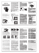
PIR Moon Sensor Installaon
a. Mount the waterproof PIR Moon Sensor
vercally on a solid surface 3-5 feet (1-1.5m)
above the ground (rotate sensor to access
screw holes). The sensor should be able
to swivel as needed. Posion the sensor
to avoid direct sunlight shining on the
sensor eye while simultaneously keeping
the solar cell facing upward.
Troubleshoong
• The PIR Moon Sensor operates, but the base
staon does not respond.
Check the sensor switch sengs (Assembly &
Seng) and make sure the sensor and base in
the valid 1/2 mile range.
• PIR Moon Sensor is detecng moon only
part of the me.
Set the PIR Sensor Switch to High sensivity
seng. To detect vehicles, The PIR sensor detects
the movements with heat sources. Please adjust
the sensor eye with horizontal angle to the engine
of the car. Swivel the sensor to obtain the best
line of sight to a vehicle.
• The system is giving false alarms.
Check for moving tree branches or insects
in the sensor window and remove as necessary.
Check the Sensor Switches on the PIR Moon
Sensor (Assembly & Seng).
Ensure that sunlight is not shining directly
onto the sensor eye.
• The system is not geng expected
transmission range.
Ensure that the PIR Moon Sensors are vercally
aligned, not aached to the far side of a tree,
and away from metal objects. Ensure that the
Base Staon has the clearest possible line of site
to the sensors. The fewer objects between the
devices, the longer the range.
Limited 24 months Warranty
EXCEPT AS PROVIDED HEREIN, SELLER MAKES NO
EXPRESS WARRANTIES AND ANY IMPLIED WARRANTIES,
INCLUDING THOSE OF MERCHANTABILITY AND
FITNESS FOR A PARTICULAR PURPOSE, ARE LIMITED
IN DURATION TO THE DURATION OF THE WRITTEN
LIMITED WARRANTIES CONTAINED HEREIN, EXCEPT
AS PROVIDED HEREIN, SELLER SHALL HAVE NO
LIABILITY OR RESPONSIBILITY TO CUSTOMER OR
ANY OTHER PERSON OR ENTITY WITH RESPECT TO
ANY LIABILITY, LOSS OR DAMAGE CAUSED DIRECTLY
OR INDIRECTLY BY USE OR PERFORMANCE OF THE
PRODUCT OR ARISING OUT OF ANY BREACH OF
THIS WARRANTY, INCLUDING, BUT NOT LIMITED
TO ANY DAMAGES RESULTING FROM INCONVENIENCE,
2 31
9 10 118
Operaon & Features
1.Base Staon
On/Off
To turn the Base Staon on or off, hold down the
Power buon unl you hear the on/off tone. The
red power light will illuminate on #3 when the
Base Staon is on.
Volume
The Base Staon is equipped with adjustable
Volume +/- controls. The lowest volume seng
mutes the volume. Volume adjustments will be
heard on subsequent alarm acvaons, not
Overview
The Wireless Moon Alert has a range of up to
1/2 mile (800 meters). It uses a Passive Infrared
(PIR) Moon Sensor to detect movement of
people and vehicles while allowing small animals
to pass through undetected. The Base Staon is
powered by an AC adapter, it can also run on
4AA baeries as backup in case of power outage
for 2 weeks.
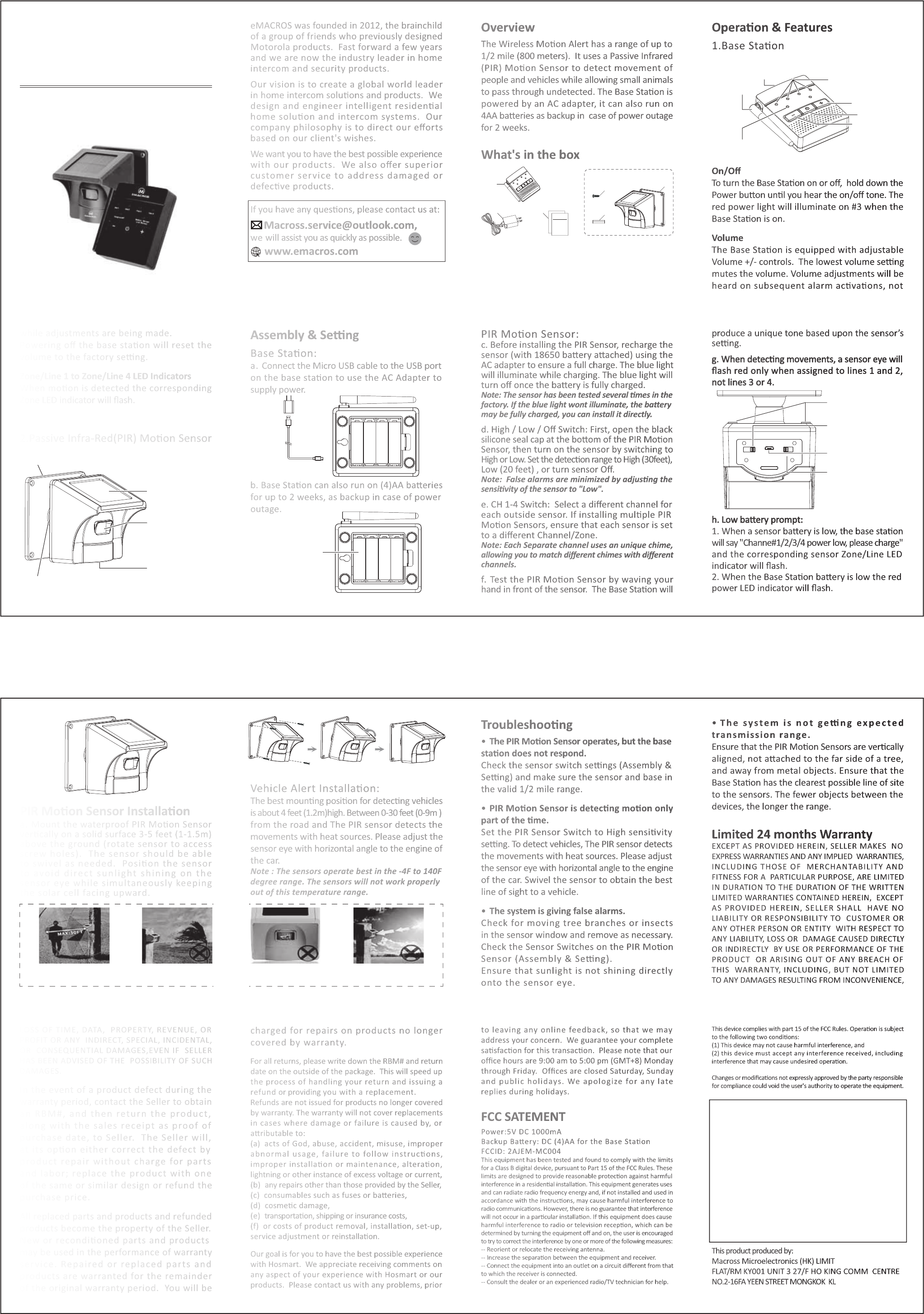
What's in the box
LOSS OF TIME, DATA, PROPERTY, REVENUE, OR
PROFIT OR ANY INDIRECT, SPECIAL, INCIDENTAL,
OR CONSEQUENTIAL DAMAGES,EVEN IF SELLER
HAS BEEN ADVISED OF THE POSSIBILITY OF SUCH
DAMAGES.
In the event of a product defect during the
warranty period, contact the Seller to obtain
an RBM#, and then return the product,
along with the sales receipt as proof of
purchase date, to Seller. The Seller will,
at its opon either correct the defect by
product repair without charge for parts
and labor; replace the product with one
of the same or similar design or refund the
purchase price.
All replaced parts and products and refunded
products become the property of the Seller.
New or recondioned parts and products
may be used in the performance of warranty
service. Repaired or replaced parts and
products are warranted for the remainder
of the original warranty period. You will be
charged for repairs on products no longer
covered by warranty.
For all returns, please write down the RBM# and return
date on the outside of the package. This will speed up
the process of handling your return and issuing a
refund or providing you with a replacement.
Refunds are not issued for products no longer covered
by warranty. The warranty will not cover replacements
in cases where damage or failure is caused by, or
aributable to:
(a) acts of God, abuse, accident, misuse, improper
abnormal usage, failure to follow instrucons,
improper installaon or maintenance, alteraon,
lightning or other instance of excess voltage or current,
(b) any repairs other than those provided by the Seller,
(c) consumables such as fuses or baeries,
(d) cosmec damage,
(e) transportaon, shipping or insurance costs,
(f) or costs of product removal, installaon, set-up,
service adjustment or reinstallaon.
Our goal is for you to have the best possible experience
with Hosmart. We appreciate receiving comments on
any aspect of your experience with Hosmart or our
products. Please contact us with any problems, prior
to leaving any online feedback, so that we may
address your concern. We guarantee your complete
sasfacon for this transacon. Please note that our
office hours are 9:00 am to 5:00 pm (GMT+8) Monday
through Friday. Offices are closed Saturday, Sunday
and public holidays. We apologize for any late
replies during holidays.
FCC SATEMENT
Power:5V DC 1000mA
Backup Baery: DC (4)AA for the Base Staon
FCCID: 2AJEM-MC004
This equipment has been tested and found to comply with the limits
for a Class B digital device, pursuant to Part 15 of the FCC Rules. These
limits are designed to provide reasonable protecon against harmful
interference in a residenal installaon. This equipment generates uses
and can radiate radio frequency energy and, if not installed and used in
accordance with the instrucons, may cause harmful interference to
radio communicaons. However, there is no guarantee that interference
will not occur in a parcular installaon. If this equipment does cause
harmful interference to radio or television recepon, which can be
determined by turning the equipment off and on, the user is encouraged
to try to correct the interference by one or more of the following measures:
-- Reorient or relocate the receiving antenna.
-- Increase the separaon between the equipment and receiver.
-- Connect the equipment into an outlet on a circuit different from that
to which the receiver is connected.
-- Consult the dealer or an experienced radio/TV technician for help.
This device complies with part 15 of the FCC Rules. Operaon is subject
to the following two condions:
(1) This device may not cause harmful interference, and
(2) this device must accept any interference received, including
interference that may cause undesired operaon.
Changes or modificaons not expressly approved by the party responsible
for compliance could void the user's authority to operate the equipment.
This product produced by:
Macross Microelectronics (HK) LIMIT
FLAT/RM KY001 UNIT 3 27/F HO KING COMM CENTRE
NO.2-16FA YEEN STREET MONGKOK KL
12 13 14 15
while adjustments are being made.
Powering off the base staon will reset the
volume to the factory seng.
Zone/Line 1 to Zone/Line 4 LED Indicators
When moon is detected the corresponding
Zone LED indicator will flash.
2.Passive Infra-Red(PIR) Moon Sensor
PIR Moon Sensor:
c. Before installing the PIR Sensor, recharge the
sensor (with 18650 baery aached) using the
AC adapter to ensure a full charge. The blue light
will illuminate while charging. The blue light will
turn off once the baery is fully charged.
Note: The sensor has been tested several mes in the
factory. If the blue light wont illuminate, the baery
may be fully charged, you can install it directly.
d. High / Low / Off Switch: First, open the black
silicone seal cap at the boom of the PIR Moon
Sensor, then turn on the sensor by switching to
High or Low. Set the detecon range to High (30feet),
Low (20 feet) , or turn sensor Off.
Note: False alarms are minimized by adjusng the
sensivity of the sensor to "Low".
e. CH 1-4 Switch: Select a different channel for
each outside sensor. If installing mulple PIR
Moon Sensors, ensure that each sensor is set
to a different Channel/Zone.
Note: Each Separate channel uses an unique chime,
allowing you to match different chimes with different
channels.
f. Test the PIR Moon Sensor by waving your
hand in front of the sensor. The Base Staon will
Assembly & Seng
Base Staon:
a. Connect the Micro USB cable to the USB port
on the base staon to use the AC Adapter to
supply power.
b. Base Staon can also run on (4)AA baeries
for up to 2 weeks, as backup in case of power
outage.
produce a unique tone based upon the sensor’s
seng.
g.
When detecng movements, a sensor eye will
flash red only when assigned to lines 1 and 2,
not lines 3 or 4.
h. Low baery prompt:
1. When a sensor baery is low, the base staon
will say "Channe#1/2/3/4 power low, please charge"
and the corresponding sensor Zone/Line LED
indicator will flash.
2. When the Base Staon baery is low the red
power LED indicator will flash.
4 5 6 7
Mounng
Plate
Ball-joint adjustment
screw(on the back)
Sensor Eye
AC Adapter input
Micro USB port
Solar Panel
Waterproof Plug
CH 1-4 Switch:
Select a different channel for
each outside sensor.
Charge Port
High / Low / Off Switch:
Set detection range to
High (30 ft),
Low (20 ft),
or turn sensor Off.
CH4 CH3 CH2 CH1 Charge Port High Low OFF
Point the sensor eye away from
direct or reflected sunlight to avoid
false alarms.
Please mount the motion sensor
3 to 4ft above the ground.
Please point the sensor in an envioronment
free from limbs, falling leaves, or other items
affected by wind which may trigger a false alarm.
Install the sensor high enough off the
ground to prevent false alarms from
dirt and small animals.
– This radio is designed for and classified as “General population/uncontrolled
Use”
– DO NOT operate the radio without a proper antenna attached, as this may
damage the radio and may also cause you to exceed RF exposure limits.
A proper antenna is the antenna supplied with this radio by the manufacturer
or an antenna specifically authorized by the manufacturer for use with this
radio, and the antenna gain shall not exceed 2dBi by the manufacturer declared.
– DO NOT transmit for more than 50% of total radio use time, more than 50%
of the time can cause RF exposure compliance requirements to be exceeded.
– During operation, the separation distance between user and the antenna
shall be at least 20cm, this separation distance will ensure that there is
sufficient distance from a properly installed externally-mounted antenna to
satisfy the RF exposure requirements
– During transmissions, your radio generates RF energy that can possibly
cause interference with other devices or systems. To avoid such interference,
turn off the radio in areas where signs are posted to do so. DO NOT operate
the transmitter in areas that are sensitive to electromagnetic radiation such
as hospitals, aircraft, and blasting sites.
Antenna
Zone 1 to Zone 4,
LED Indicator
Volume+
Power on/off
LED indicate
Volume-
Power
AC Adapter input
Micro USB port
Model:HY-002
WIRELESS
DRIVEWAY ALARM
INSTRUCTION MANUAL
Model:HY-002
2
1
3
PIR Sensor package
4
6
5
1 Base Station
2 AC Adapter
3 Documentation
4 sensor back plate screws
5 masonry screw anchors
6 PIR Motion Sensor
Install 4xAA
baeries
(Oponal)
+
-
+
-
AC Adapter
(Recommended)
WIRELESS SOLAR
DRIVEWAY ALARM
INSTRUCTION MANUAL
MODEL:MC-004