Form No. 3393-656 Rev A TimeCutter® SW 4200 or SW 5000 Riding Mower Model No. 74675—Serial No. 315000001 and Up Model No. 74680—Serial No. 315000001 and Up g027698 Register at www.Toro.com.
This product complies with all relevant European directives; for details, please see the separate product specific Declaration of Conformity (DOC) sheet. 1 Gross Horsepower The gross or net horsepower of this engine was laboratory rated by the engine manufacturer in accordance with the Society of Automotive Engineers (SAE) J1940. As configured to meet safety, emission, and operating requirements, the actual engine torque on this class of mower will be significantly lower. G014523 Go to www.Toro.
Cleaning and Storage ..............................................52 Troubleshooting ...........................................................53 Schematics ...................................................................55 Breaking in a New Machine......................................18 Think Safety First ...................................................19 Starting the Engine .................................................21 Operating the Parking Brake (SmartPark™) ................
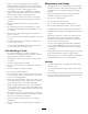
Preparation Safety • Evaluate the terrain to determine what accessories and This machine has been designed in accordance with EN ISO 5395:2013. Improperly using or maintaining this mower can result in injury. To reduce the potential for injury, comply with these safety instructions. • Toro designed and tested this mower for reasonably safe service; however, failure to comply with the following instructions may result in personal injury.
Maintenance and Storage • Stop on level ground, disengage drives, engage the • • • • • • • • • parking brake (if provided), shut off the engine before leaving the operator's position for any reason, including emptying the catchers or unclogging the chute. Stop equipment and inspect the blades after striking objects or if an abnormal vibration occurs. Make the necessary repairs before resuming operations. Keep your hands and feet away from the cutting unit.
Toro Mower Safety Slope Operation The following list contains safety information specific to Toro products and other safety information you must know. All slopes and ramps require extra caution. If you feel uneasy on a slope, do not mow it. • Remove obstacles such as rocks, tree limbs, etc. from the mowing area. • Watch for holes, ruts or bumps. This product is capable of amputating hands and feet, and throwing objects. Always follow all safety instructions to avoid serious injury or death.
Model 74680 • Replace all parts including, but not limited to, tires, belts, blades, and fuel system components with original Toro parts. Sound Pressure • Check brake operation frequently. Adjust and service as required. This unit has a sound pressure level at the operator’s ear of 93 dBA, which includes an Uncertainty Value (K) of 1 dBA. Model 74675 Sound power level was determined according to the procedures outlined in EN ISO 5395:2013.
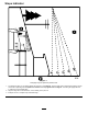
Slope Indicator G011841 Figure 3 This page may be copied for personal use. 1. The maximum slope you can safely operate the machine on is 15 degrees. Use the slope chart to determine the degree of slope of hills before operating. Do not operate this machine on a slope greater than 15 degrees. Fold along the appropriate line to match the recommended slope. 2. Align this edge with a vertical surface, a tree, building, fence pole, etc. 3. Example of how to compare slope with folded edge.
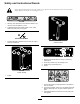
Safety and Instructional Decals Safety decals and instructions are easily visible to the operator and are located near any area of potential danger. Replace any decal that is damaged or lost. 93-7009 1. Warning—don't operate the mower with the deflector up or removed; keep the deflector in place. 2. Cutting/dismemberment hazard of hand or foot, mower blade—stay away from moving parts. Manufacturer's Mark 105-7015 Certain models 1.
112-9840 1. Read the Operator's Manual. 3. Remove the ignition key and read the instructions before servicing or performing maintenance. 2. Height-of-cut 114-1606 120-5470 Certain models 1. Entanglement hazard, belt—keep all guards in place. 1. Height-of-cut 121-2989 1. Bypass lever position for pushing the machine 120-5469 Certain models 1. Height-of-cut 10 2.
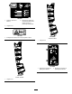
Battery Symbols Some or all of these symbols are on your battery 1. Explosion hazard 6. Keep bystanders a safe distance from the battery. 2. No fire, open flame, or smoking. 7. Wear eye protection; explosive gases can cause blindness and other injuries 3. Caustic liquid/chemical burn hazard 4. Wear eye protection 8. Battery acid can cause blindness or severe burns. 9. Flush eyes immediately with water and get medical help fast. 5. Read the Operator's Manual. 131-3620 1. Pedal position—forward 3.
131-3665 1. Blade spinning 3. Read the Operator's Manual. 2. Reverse 131-3954 1. On 2. Off 131-3955 1. On 2. Off 131-4036 1. The maximum drawbar pull is 36 kg (80 lb). 2. Read the Operator's Manual.
2-0870 1. Warning—read the Operator's Manual. 3. Bodily harm hazard—no riders; look behind you when mowing in reverse. 5. Ramp tipping hazard—when loading onto a trailer, do not use dual ramps; only use a single ramp wide enough for the machine and that has an incline less than 15 degrees; back up the ramp (in reverse) and drive forward off the ramp. 2. Cutting hazard of hand, mower blade; pinching hazard of hand, belt—keep hands and feet away from moving parts; keep all guards and shields in place.
121-0772 1. Fast 2. Continuous-variable setting 4. Choke 5. Power take-off (PTO), blade-control switch 3.
121-0773 1. Fast 2. Continuous-variable setting 4. Choke 5. Power take-off (PTO), blade-control switch 3.
Product Overview 6 7 5 3 8 4 2 1 Figure 6 1. Operating–in–Reverse warning light 3. Fuel-presence window 2. Key Choice key (blue in color) 9 10 11 12 Ignition Switch g027935 The ignition switch has 3 positions—Off, Run and Start. The key will turn to Start and move back to Run upon release. Turning the key to the Off position will stop the engine; however, always remove the key when leaving the machine to prevent someone from accidentally starting the engine (Figure 5). Figure 4 1.
Key Choice® Switch Operation This switch allows you to mow in reverse when it is activated. To activate it, turn the switch to on and release it after the PTO is engaged. To deactivate it, disengage the power take-off (PTO) (Figure 6). Note: Determine the left and right sides of the machine from the normal operating position.
Note: A fuel stabilizer/conditioner is most effective when mixed with fresh gasoline. To minimize the chance of varnish deposits in the fuel system, use fuel stabilizer at all times. DANGER In certain conditions during fueling, static electricity can be released causing a spark which can ignite the gasoline vapors. A fire or explosion from gasoline can burn you and others and can damage property.
Think Safety First CAUTION This machine produces sound levels in excess of 85 dBA at the operators ear and can cause hearing loss through extended periods of exposure. Operating Safety Please carefully read all of the safety instructions and decals in the safety section. Knowing this information could help you, your family, pets, or bystanders avoid injury. Wear hearing protection when operating this machine. DANGER The use of protective equipment for eyes, ears, feet, and head is recommended.
Understanding the Safety-interlock System Note: The engine should remain running. 9. Return to the seat, disengage the parking brake by pushing the SmartPark switch to the Off position. WARNING Note: The engine should remain running. If safety-interlock switches are disconnected or damaged, the machine could operate unexpectedly causing personal injury. 10. Raise from the seat. Note: The brake should automatically engage and the engine should remain running.
Starting the Engine Operating the Blades Important: Do not engage the starter for more than 5 seconds at a time. Engaging the starter motor for more than 5 seconds can damage the starter motor. If the engine fails to start, wait 10 seconds before operating the engine starter again. The blade control switch, represented by a power take-off (PTO) symbol, engages and disengages power to the mower blades.
Stopping the Engine 1. Disengage the blades by pushing the blade-control switch to Off (Figure 12). 2. Move the throttle lever to the Fast position. 3. Turn the ignition key to Off and remove the key. Driving the Machine Figure 13 This machine has the characteristics of both a garden tractor and a zero-turn machine.
Stopping the Machine 4. Perform the mowing. To stop the machine, release the traction-control pedal, disengage the blade-control switch, ensure the throttle is in the fast positions, set the parking brake and turn the ignition key to off. 5. When finished mowing, remove the KeyChoice key (Figure 6).
Adjusting the Anti-scalp Rollers (for 107 cm (42-inch) Mower Decks) Positioning the Seat A B Whenever you change the height-of-cut, it is recommended to adjust the height of the anti-scalp rollers. Note: Adjust the anti-scalp rollers so the rollers do not touch the ground in normal, flat mowing areas. 1. Disengage the blade-control switch (PTO) and ensure the parking brake is engaged. 2. Stop the engine, remove the key, and wait for all moving parts to stop before leaving the operating position. C 3.
3 2. Stop the engine, remove the key, and wait for all moving parts to stop before leaving the operating position. 3. Adjust the anti-scalp rollers (Figure 18) to match the closest height-of-cut position. 4 G010233 3 1 1 2 Figure 18 1. Anti-scalp roller 3. Flange nut 2. Bolt 4. Hole spacing 2 g017303 Figure 19 1. Bypass-lever locations 3. Lever position for pushing the machine 2. Lever position for operating the machine 6.
Converting to Side Discharge (for models with 107 cm (42-inch) decks) The mower deck and mower blades shipped with this machine were designed for optimum mulching and side discharge performance. 1 Removing the Discharge Cover for the Side Discharge 2 3 1. Park the machine on a level surface and disengage the blade-control switch. G005667 Figure 21 2. Ensure the parking brake is engaged, stop the engine, remove the key, and wait for all moving parts to stop before leaving the operating position. 1.
4. Remove the 2 knobs and curved washers that secure the right baffle to the mower (Figure 23). Figure 23 1. Knob 3. Baffle stud coming through the mower 2. Curved washer 5. Remove the right baffle and lower the grass deflector over the discharge opening as shown in Figure 23 and Figure 24. Figure 22 1. Discharge cover 3. Bolt (1/4 x 2-1/2 inches) 2. Cap nut (1/4 inch) 6.
Installing the Right Baffle for Mulching WARNING 1. Park the machine on a level surface and disengage the blade-control switch. Open holes in the mower expose you and others to thrown debris which can cause severe injury. 2. Ensure the parking brake is engaged, stop the engine, remove the key, and wait for all moving parts to stop before leaving the operating position. • Never operate the mower without hardware mounted in all holes in the mower housing. 3.
Transporting the Machine Loading the Machine Use a heavy-duty trailer or truck to transport the machine. Ensure that the trailer or truck has all necessary brakes, lighting, and marking as required by law. Please carefully read all the safety instructions. Knowing this information could help you, your family, pets, or bystanders avoid injury. Use extreme caution when loading or unloading machines onto a trailer or a truck. Use a full-width ramp that is wider than the machine for this procedure.
WARNING 1 Loading a machine onto a trailer or truck increases the possibility of tip-over and could cause serious injury or death. • Use extreme caution when operating a machine on a ramp. • Use only a full-width ramp; do not use individual ramps for each side of the machine. • Do not exceed a 15-degree angle between the ramp and the ground or between the ramp and the trailer or truck.
Operating Tips lawn. To avoid this, move onto a previously cut area with the blades engaged or you can disengage the mower deck while moving forward. Using the Fast Throttle Setting For best mowing and maximum air circulation, operate the engine at the Fast throttle position. Air is required to thoroughly cut grass clippings, so do not set the height-of-cut so low as to totally surround the mower by uncut grass.
Maintenance Note: Determine the left and right sides of the machine from the normal operating position. Recommended Maintenance Schedule(s) Maintenance Service Interval Maintenance Procedure After the first 5 hours • Change the engine oil. Before each use or daily • • • • Check the engine-oil level. Clean the air-intake screen. Check the cutting blades. Inspect the grass deflector for damage After each use • Check and clean the front of the machine. • Clean the mower-deck housing.
Premaintenance Procedures Raising the Front of the Machine If the front of the machine needs to be raised, use the very front edge as show in Figure 30. Raising the Seat Important: To prevent damage to the steering mechanism, ensure the very front edge of the machine is used for jacking points. Ensure the parking brake is engaged and lift the seat forward.
Lubrication Engine Maintenance Greasing the Bearings Servicing the Air Cleaner Service Interval: Every 25 hours—Grease all the lubrication points. Note: Service the air cleaner more frequently (every few hours) if operating conditions are extremely dusty or sandy. Grease Type: No. 2 general purpose, lithium-base grease Removing the Elements 1. Park the machine on a level surface, and disengage the blade-control switch. 1.
g027802 Figure 34 Figure 35 Servicing the Foam Element Service Interval: Every 25 hours/Monthly (whichever comes first)—Clean the foam element (more often in dusty, dirty conditions). Checking the Engine-Oil Level Service Interval: Before each use or daily Every 100 hours/Yearly (whichever comes first)—Replace the foam element (more often in dusty, dirty conditions). Note: Check the oil when the engine is cold. WARNING Wash the foam element with water and replace the foam element if it is damaged.
A B C D E g027799 F H A B C D E F G I J G027475 Figure 36 Changing the Engine Oil Service Interval: After the first 5 hours/After the first month (whichever comes first)—Change the engine oil. Every 100 hours/Yearly (whichever comes first)—Change the engine oil (more often in dusty, dirty conditions). Note: Dispose of the used oil at a recycling center. G 1. Park the machine so that the drain side is slightly lower than the opposite side to assure the oil drains completely. 2.
Changing the Engine-Oil Filter 4. Change the oil filter before adding engine oil. Refer to Changing the Engine-Oil Filter (page 37). Service Interval: Every 100 hours/Yearly (whichever comes first)—Change the oil filter (more often in dusty, dirty conditions). 5. Slowly pour approximately 80% of the specified oil into the filler tube and slowly add the additional oil to bring it to the Full mark (Figure 38).
wrench for removing and installing the spark plug(s) and a gapping tool/feeler gauge to check and adjust the air gap. Install a new spark plug(s) if necessary. B A Type: Champion RN9YC Air gap: 0.76 mm (0.03 inch) Removing the Spark Plug C 1. Disengage the PTO and ensure the parking brake is engaged. 25-30 N-m 18.5-22.1 ft-lb D 2. Stop the engine, remove the key, and wait for all moving parts to stop before leaving the operating position.
Fuel System Maintenance DANGER In certain conditions, gasoline is extremely flammable and highly explosive. A fire or explosion from gasoline can burn you, others, and can damage property. g027939 A • Perform any fuel-related maintenance when the engine is cold. Do this outdoors in an open area. Wipe up any gasoline that spills. • Never smoke when draining gasoline, and stay away from an open flame or where a spark may ignite the gasoline fumes.
Electrical System Maintenance 5. Slide the rubber cover up the positive (red) cable. Disconnect the positive (red) cable from the battery post (Figure 44). Retain all fasteners. 6. Remove the battery hold-down (Figure 44) and lift the battery from the battery tray. WARNING CALIFORNIA Proposition 65 Warning Battery posts, terminals, and related accessories contain lead and lead compounds, chemicals known to the State of California to cause cancer and reproductive harm. Wash hands after handling.
Servicing the Fuses The electrical system is protected by fuses. It requires no maintenance; however, if a fuse blows, check the component/circuit for a malfunction or short. Fuse type: • Main—F1-30 amp, blade-type • Charge Circuit—F2-25 amp, blade-type 1. Remove the screws securing the control panel to the machine. Figure 45 1. Positive battery post 3. Red (+) charger lead 2. Negative battery post 4. Black (-) charger lead Note: Retain all fasteners. 2.
Drive System Maintenance 2. Locate the shaft on the electric brake where the brake link arms are connected. 3. Rotate the shaft forward to release the brake. Checking the Tire Pressure Service Interval: Every 25 hours—Check tire pressure. Maintain the air pressure in the front and rear tires as specified. Uneven tire pressure can cause uneven cut. Check the pressure at the valve stem (Figure 47). Check the tires when they are cold to get the most accurate pressure reading.
Mower Maintenance Servicing the Cutting Blades Maintain sharp blades throughout the cutting season, because sharp blades cut cleanly without tearing or shredding the grass blades. Tearing and shredding turns grass brown at the edges, which slows growth, and increases the chance of disease. Figure 49 Check the cutter blades daily for sharpness, and for any wear or damage. File down any nicks and sharpen the blades as necessary.
3. Measure from the tip of the blade to the flat surface (Figure 51). 1 1 G014973 3 2 G014973 3 Figure 53 2 1. Opposite blade edge (in position for measuring) Figure 51 2. Level surface 3. Second measured distance between blade and surface (B) 1. Blade (in position for measuring) 2. Level surface 3. Measured distance between blade and the surface (A) A.
Important: The curved part of the blade must be pointing upward toward the inside of the mower to ensure proper cutting. 2. Install the curved washer (cupped side toward the blade) and the blade bolt (Figure 54). 3. Torque the blade bolt to 47 to 88 N-m (35 to 65 ft-lb). Leveling the Mower Deck Check to ensure that the mower deck is level any time you install the mower or when you see an uneven cut on your lawn.
G005278 2 9. Check the side-to-side adjustments again. Repeat this procedure until the measurements are correct. 10. Continue leveling the mower deck by checking the front-to-rear blade slope; refer to Adjusting the Front-to-Rear Blade Slope (page 46). 3 3 1 Adjusting the Front-to-Rear Blade Slope 2 4 Check the front-to-rear blade level any time you install the mower. If the front of the mower is more than 7.
3 10. When the front-to-rear blade slope is correct check the side-to-side level of the mower again, refer to Side-to-Side Leveling (page 45). 2 Removing the Mower 1 G009659 2 1. Park the machine on a level surface and disengage the blade-control switch. 3 2. Ensure the parking brake is engaged, stop the engine, remove the key, and wait for all moving parts to stop before leaving the operating position. Figure 61 Mower decks with 3 Blades 1. Blades front to rear 3.
Replacing the Grass Deflector Service Interval: Before each use or daily—Inspect the grass deflector for damage WARNING 2 An uncovered discharge opening could allow the lawn mower to throw objects in the operator's or bystander's direction and result in serious injury. Also, contact with the blade could occur. 2 3 Never operate the machine without the grass deflector, the discharge cover, or the grass-collection system in place. 1 G005077 Inspect the grass deflector for damage before each use.
Mower Belt Maintenance 9. Secure the rear end of the rod into the mower with a nut (3/8 inch) as shown in Figure 65. Important: The grass deflector must be spring loaded and in the down position. Lift the deflector up to test that it snaps to the full down position. Inspecting the Belts Service Interval: Every 25 hours—Check the belts for wear or cracks. Check the belts for cracks, frayed edges, burn marks, or any other damage. Replace damaged belts.
7. Using a spring-removal tool, install the idler spring over the deck hook, and place tension on the idler pulley and mower belt (Figure 66 and Figure 67). 2 8. Tighten the bottom 2 bolts for the mower-deck curtain to the mower deck. Refer to Releasing the Mower-Deck Curtain (page 33). 5 1 3 4 3 4 G014930 6 Figure 66 Mower decks with 2 Blades 1. Idler pulley 4. Spring 2. Mower belt 5. Engine pulley 3. Outside pulley 6.
Cleaning Cleaning Under the Front of the Machine Service Interval: After each use—Check and clean the front of the machine. Remove debris under the front of the machine with compressed air or by hand with a brush (Figure 68). Note: Do not use water to clean under the front of the machine, this can cause build up of debris. Figure 69 1. Washout fitting 3. O-ring 2. Hose 4. Coupling 4. Lower the mower to the lowest height-of-cut. 5. Sit on the seat and start the engine. 6.
Storage plug(s) removed from the engine, pour two tablespoons of engine oil into the spark plug hole. Use the starter to crank the engine and distribute the oil inside the cylinder. Install the spark plug(s). Do not install the wire on the spark plug(s). Cleaning and Storage 1. Disengage the blade-control switch, move the motion controls outward to the park position, stop the engine, and remove the key. 13. Clean any dirt and chaff from the top of the mower. 14.
Troubleshooting Problem Possible Cause The fuel tank is showing signs of collapsing or the machine is showing signs of frequently running out of fuel. 1. The air cleaner paper element clogged. 1. Clean the paper element. The engine overheats. 1. The engine load is excessive. 1. Reduce ground speed. 2. The oil level in the crankcase is low. 3. The cooling fins and air passages under the engine blower housing are plugged. 4. The air cleaner is dirty. 2. Add oil to the crankcase. 3.
Problem There is abnormal vibration. Uneven cutting height. Possible Cause 1. The engine mounting bolts are loose. 1. Tighten the engine mounting bolts. 2. The engine pulley, idler pulley, or blade pulley is loose. 3. The engine pulley is damaged. 4. The cutting blade(s) is/are bent or unbalanced. 5. A blade mounting bolt is loose. 6. A blade spindle is bent. 2. Tighten the appropriate pulley. 5. Tighten the blade mounting bolt. 6. Contact an Authorized Service Dealer. 1. The blade(s) is not sharp.
Schematics Electrical Diagram (Rev.
Notes: 56
Notes: 57
Notes: 58
International Distributor List Distributor: Country: Phone Number: Distributor: Phone Number: 57 1 236 4079 Colombia Japan 81 3 3252 2285 Czech Republic 420 255 704 220 420 255 704 Slovakia 220 Argentina 54 11 4 821 9999 Russia 7 495 411 61 20 Ecuador 593 4 239 6970 Finland 358 987 00733 Agrolanc Kft Balama Prima Engineering Equip. B-Ray Corporation Hungary Hong Kong Korea 36 27 539 640 852 2155 2163 82 32 551 2076 Maquiver S.A. Maruyama Mfg. Co. Inc. Mountfield a.s.
Residential Products The Toro Warranty and The Toro GTS Starting Guarantee Conditions and Products Covered Owner Responsibilities The Toro Company and its affiliate, Toro Warranty Company, pursuant to an agreement between them, jointly promise to repair for the original purchaser1the Toro Product listed below if defective in materials or workmanship or if the Toro GTS (Guaranteed to Start) engine will not start on the first or second pull, provided the routine maintenance required in the Operator's Manua