
Product Manual


6
EMAX Rotary Screw Compressors
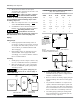
2. Allow at least 24 inches of clear space
around the sides and back and at least 3 feet
in front of the compressor.
This compressor unit is equipped
with internal rubber vibration
isolators. To avoid internal pump damage, DO NOT
use an additional rubber mounting surface when
installing compressor.
3. Make sure compressor base is on a hard, flat
surface and anchored securely.
4. If installation is above the first story of a
building, use appropriate vibration insulation.
Tank Sizing Guideline: Tank
capacity must be at least 1.2
gallons for every CFM of air produced by compressor.
This will minimize wear on internal pump parts.
Piping
Safety Steps
1. Install appropriate flow-limiting valves as
necessary according to pipe size(s) used and
run lengths. This will reduce pressure in case
of hose failure, per OSHA Standard 29 CFR
1926.302(b)(7).
2. Flow-limiting valves are listed by pipe size
and rated CFM. Select appropriate valves
accordingly, in accordance with the manufac-
turer’s recommendations.
Installing
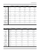
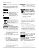
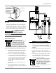
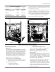
1. Install piping as shown in Figure 4. Refer to fig-
ure 5 for recommended closed loop installation.
2. Make sure any tube, pipe or hose connected to
the unit can withstand operating temperatures
and retain pressure.
Never use plastic (PVC) pipe for
compressed air. Serious injury or
death could result.
3. Install appropriate ASME code safety valves
and make sure piping system is equipped with
adequate condensate drains.
4. Never use reducers in discharge piping. Keep all
piping and fittings the same size in the piping
system.
5. For permanent installations of compressed air
systems, determine total length of system and
select correct pipe size. Make sure underground
lines are buried below frost line and avoid areas
where condensation could build up and freeze.
6. Test entire piping system before underground
lines are buried. Be sure to find and repair all
leaks before using compressor.
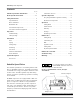
Minimum Pipe Size For Compressed Air Lines
(Pipe size shown in inches)
Length Of Piping System
SCFM 25 ft. 50 ft. 100 ft. 250 ft.
20 3/4 3/4 3/4 1
40 3/4 1 1 1
60 3/4 1 1 1
100 1 1 1 1-1/4
125 1-1/4 1-1/4 1-1/2 1-1/2
150 1-1/2 2 2 2
200 2 2 2 2
Rotary Screw
Compressor
Cabinet
Ball
Valve
Ball Valve
Water Drain Valve
Air
Storage
Tank
Air Dryer
Coalescing Filter
with Auto Drain
To Shop
Piping
Water trap
with drain
Air Drop
(typ.)
Air Drop:
Install tee fitting with branch to top
to minimize condensation in air drop
PLAN VIEW
Closed loop system
Install tee fitting
in piping from air
supply to minimize
pressure drop and to
allow airflow in two
directions.
ELEVATION
From
Compressor
From Compressor
To Air Tool
Figure 4: Basic Piping Diagram
Figure 5: Closed Loop Installation